Q-Tech QT66T User Manual
Page 4
MIL-PRF-55310/19E
4
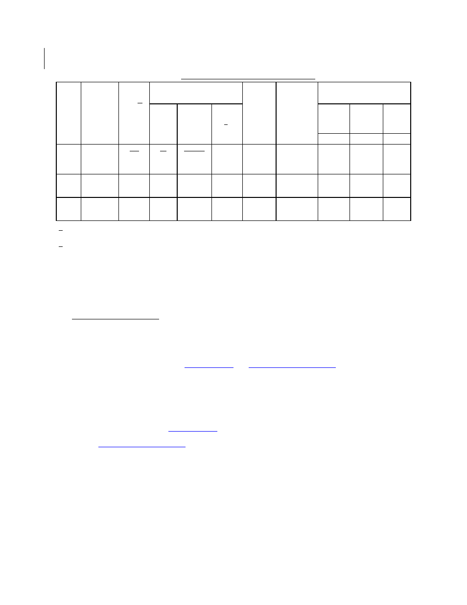
TABLE I. Dash numbers and operating characteristics.
1/ Maximum input current for no load condition. Actual configuration of TTL loads must be added to determine
power supply requirements.
2/ A TTL unit load is defined as: 1.6 mA sink, 0.04 mA source, and 2pF capacitance.
Frequency-voltage tolerance:
4 ppm maximum for a 10 percent change in supply voltage. Measurements taken
at reference temperature and operating temperature range end points.
Frequency aging: Measurements shall be taken at +70
C 0.2C at intervals of not more than every 72 hours for
30 days minimum (see table I).
10 ppm per year, maximum
1.5 ppm per 30 days.
3 ppm per 90 days.
Frequency-environmental tolerance: Not applicable.
Vibration, sinusoidal: In accordance wi
Nonoperating: Test condition G.
Operating: Not required.
Ambient pressure:
Nonoperating: In accordance wi
Reflow soldering: Reflow soldering of the unit at +230
C 10C for 15 seconds shall not degrade the performance.
Dash
num-
ber
Output
frequency
range
Input
current
max 1/
Pulse characteristics
Initial
accuracy
ppm
at
+23
C
1C
Frequency
aging
ppm/year
after
30 days
Frequency-temperature
tolerance (ppm)
Rise
and
fall
times
(max)
Duty
cycle at
1.4 V
Load
max
2/
-55
C
to
+125
C
-55
C
to
+105
C
-20
C
to
+70
C
A B C
mA ns percent
01
02
03
1.0 MHz
to
16.0 MHz
75
75
75
15
15
15
40 to 60
40 to 60
40 to 60
10 TTL
10 TTL
10 TTL
25
25
15
10
10
5
100
200
50
75
150
40
50
100
25
11
12
13
16.0 MHz
to
40.0 MHz
40
40
40
5
5
5
40 to 60
40 to 60
40 to 60
10 TTL
10 TTL
10 TTL
25
25
15
10
10
5
100
200
50
75
150
40
50
100
25
21
22
23
40.0 MHz
to
60.0 MHz
70
70
70
5
5
5
40 to 60
40 to 60
40 to 60
10 TTL
10 TTL
10 TTL
25
25
15
10
10
5
100
200
50
75
150
40
50
100
25