Q-tech, Qt89 series, Thermal characteristics – Q-Tech QT89 User Manual
Page 4
4
Q-TECH Corporation - 10150 W. Jefferson Boulevard, Culver City 90232 - Tel: 310-836-7900 - Fax: 310-836-2157 - www.q-tech.com
QT89 SERIES
HIGH-RELIABILITY MINIATURE CLOCK OSCILLATORS
1.8 to 5.0Vdc - 15kHz to 160MHz
Q-TECH
CORPORATION
QT89 (Revision J, January 2011) (ECO #10087)
Reflow and Soldering Techniques
Environmental Specifications
Q-Tech Standard Screening/QCI (MIL-PRF55310) is available for all of our QT89 Products. Q-Tech can also customize screening
and test procedures to meet your specific requirements. The QT89 product is designed and processed to exceed the following test
conditions:
Environmental Test
Test Conditions
Temperature cycling
MIL-STD-883, Method 1010, Cond. B
Constant acceleration
MIL-STD-883, Method 2001, Cond. A, Y1
Seal: Fine and Gross Leak
MIL-STD-883, Method 1014, Cond. A and C
Burn-in
160 hours, 125°C with load
Aging
30 days, 70°C, ±1.5ppm max
Vibration sinusoidal
MIL-STD-202, Method 204, Cond. D
Shock, non operating
MIL-STD-202, Method 213, Cond. I (See Note 1)
Thermal shock, non operating
MIL-STD-202, Method 107, Cond. B
Ambient pressure, non operating
MIL-STD-202, 105, Cond. C, 5 minutes dwell time minimum
Resistance to solder heat
MIL-STD-202, Method 210, Cond. C
Moisture resistance
MIL-STD-202, Method 106
Terminal strength
MIL-STD-202, Method 211, Cond. C
Resistance to solvents
MIL-STD-202, Method 215
Solderability
MIL-STD-202, Method 208
ESD Classification
MIL-STD-883, Method 3015, Class 1 HBM 0 to 1,999V
Moisture Sensitivity Level
J-STD-020, MSL=1
Unless otherwise specified, soldering should be performed on terminals at 260ºC for 10s maximum. Do not apply soldering heat on
oscillator package since it could damage the unit. Hand soldering is recommended. Wave solder at 245ºC for 15s max.
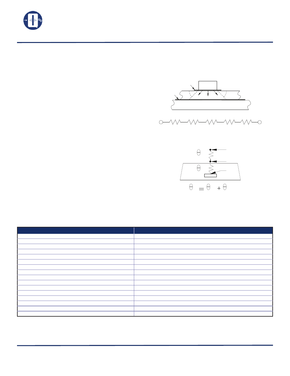
The heat transfer model in a hybrid package is described in
figure 1.
Heat spreading occurs when heat flows into a material layer of
increased cross-sectional area. It is adequate to assume that
spreading occurs at a 45° angle.
The total thermal resistance is calculated by summing the
thermal resistances of each material in the thermal path be-
tween the device and hybrid case.
RT = R1 + R2 + R3 + R4 + R5
The total thermal resistance RT (see figure 2) between the heat
source (die) to the hybrid case is the Theta Junction to Case
(Theta JC) in°C/W.
• Theta junction to case (Theta JC) for this product is 30°C/W.
• Theta case to ambient (Theta CA) for this part is 100°C/W.
• Theta Junction to ambient (Theta JA) is 130°C/W.
Maximum power dissipation PD for this package at 25°C is:
• PD(max) = (TJ (max) – TA)/Theta JA
• With TJ = 175°C (Maximum junction temperature of die)
• PD(max) = (175 – 25)/130 = 1.15W
45º
45º
Hybrid Case
Substrate
Die
D/A epoxy
D/A epoxy
Heat
Die
R1
D/A epoxy
Substrate
D/A epoxy
Hybrid Case
R2
R3
R4
R5
JA
JC
CA
Die
T
T
T
C
A
J
CA
JC
(Figure 1)
(Figure 2)
Thermal Characteristics
Note 1: Additional shock results successfully passed on standard QT88 family 16MHz, 20MHz, 24MHz, 40MHz, and 80MHz
• Shock 850g peak, half-sine, 1 ms duration (MIL-STD-202, Method 213, Cond. D modified)
• Shock 1,500g peak, half-sine, 0.5ms duration (MIL-STD-883, Method 2002, Cond. B)
• Shock 36,000g peak, half-sine, 0.12 ms duration
Please contact Q-Tech for higher shock requirements