Q-Tech QT4T User Manual
Page 4
MIL-PRF-55310/14H
4
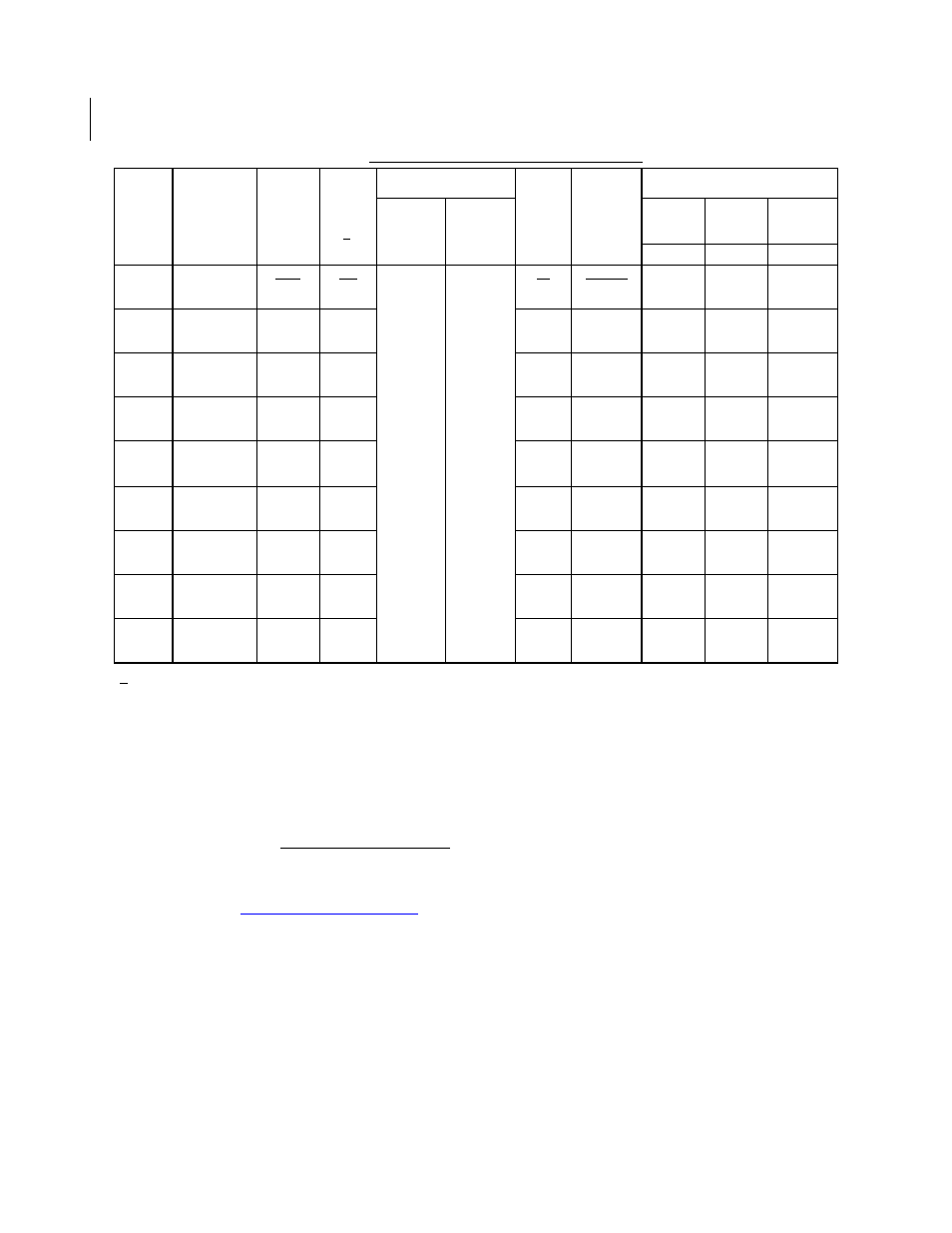
TABLE I. Dash numbers and operating characteristics.
1/ Maximum input current for no load condition. Actual configuration of TTL loads must be added to determine
power supply requirements.
Frequency-voltage tolerance:
2 ppm maximum for a 10 percent change in supply voltage. Measurements taken
at reference temperature and operating temperature range end points.
Frequency aging: Measurements shall be taken at +70
C 0.2C at intervals of not more than every 72 hours for
30 days minimum.
5 ppm per year, maximum
0.7 ppm per 30 days
1.5 ppm per 90 days
Te
Applied force: 2 pounds each terminal for 10 seconds.
Bends: Five at 45 degrees each.
Frequency-environmental tolerance: Not applicable.
Dash
num-
ber
Output
frequency
range
Supply
voltage
Input
current
(max)
1/
Output voltage
Rise
and
fall
times
(max)
Duty
cycle
at
1.4 V
Frequency-temperature
tolerance (ppm)
Logic: 1
(min)
Logic: 0
(max)
-55
C
to
+125
C
-55
C
to
+105
C
-20
C
to
+70
C
A B C
V
dc mA
ns percent
01
0.1 Hz to
1 kHz
+5
0.5
158
15
45 to 55
50
40
30
02
1 kHz to
150 kHz
+5
0.5
158
15
45 to 55
50
40
30
03
150 kHz to
300 kHz
+5
0.5
94
15
45 to 55
50
40
30
04
300 kHz to
600 kHz
+5
0.5
94
15
45 to 55
50
40
30
05
600 kHz to
2.5 MHz
+5
0.5
50
2.4 V dc
at
400
A
0.5 V dc
at 16 mA
sink
15
45 to 55
50
40
30
06
2.5 MHz to
5 MHz
+5
0.5
40
source
15
45 to 55
50
40
30
07
5 MHz to
10 MHz
+5
0.5
30
15
45 to 55
50
40
30
08
10 MHz to
15 MHz
+5
0.5
20
15
40 to 60
50
40
30
09
15 MHz to
25 MHz
+5
0.5
20
5
40 to 60
50
40
30