Q-tech, Phase noise and phase jitter integration, Revision history – Q-Tech QT83 User Manual
Page 6
6 of 6
Q-TECH Corporation - 10150 W. Jefferson Boulevard, Culver City 90232 - Tel: 310-836-7900 - Fax: 310-836-2157 - www.q-tech.com
QPDS-0002, Rev H, September 2013 (ECO# 10964)
Q-TECH
CORPORATION
LOW PROFILE QT81, QT82, QT83
MINIATURE CLOCK OSCILLATORS
1.8 to 5.0Vdc - 500kHz to 160MHz
Phase noise is measured in the frequency domain, and is expressed as a ratio of signal power to noise power measured in a 1Hz bandwidth
at an offset frequency from the carrier, e.g. 10Hz, 100Hz, 1kHz, 10kHz, 100kHz, etc. Phase noise measurement is made with an Agilent
E5052A Signal Source Analyzer (SSA) with built-in outstanding low-noise DC power supply source. The DC source is floated from the
ground and isolated from external noise to ensure accuracy and repeatability.
In order to determine the total noise power over a certain frequency range (bandwidth), the time domain must be analyzed in the frequency
domain, and then reconstructed in the time domain into an rms value with the unwanted frequencies excluded. This may be done by
converting L(f) back to Sφ(f) over the bandwidth of interest, integrating and performing some calculations.
Phase Noise and Phase Jitter Integration
The value of RMS jitter over the bandwidth of interest, e.g. 10kHz to 20MHz, 10Hz to 20MHz, represents 1 standard deviation of phase
jitter contributed by the noise in that defined bandwidth.
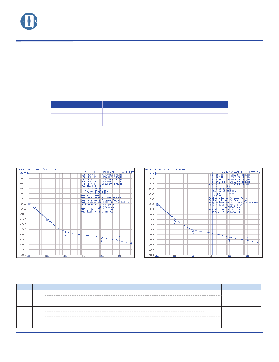
Figure below shows a typical Phase Noise/Phase jitter of a QT82LD10M, 3.3Vdc, 32MHz and QT83HCD10M, 5.0Vdc, 40MHz clock
at offset frequencies 10Hz to 1MHz, and phase jitter integrated over the bandwidth of 12kHz to 1MHz.
QT83HCD10M, 5.0Vdc, 40MHz
QT82LD10M, 3.3Vdc, 32MHz
Symbol
Definition
∫L(f)
Integrated single side band phase noise (dBc)
Sφ (f)=(180/Π)x
√
2 ∫L(f)df
Spectral density of phase modulation, also known as RMS phase error (in degrees)
RMS jitter = Sφ (f)/(fosc.360°)
Jitter(in seconds) due to phase noise. Note Sφ (f) in degrees.
ECO REV
REVISION SUMMARY
Page
Date
10613
F
Add Solder Dip option G
1
7/16/2012
Add dimension tolerance to QT82 & QT83 outlines
Modified Package Material From 90% AL2O3 to 91% AL2O3
3
10719
G
Features: Modified
36000G shock to half sine, 0.5ms
1
2/13/2013
Ordering Information: Added Frequency vs. Temperature code 17 & 18
Change Rise and Fall Time from 30MHz to 40MHz
2
10964
H
Modified Outline QT82 & QT83 Lead form dimensions
3
9/4/2013
Revision History