Q-tech, Leadless chip carrier, 5 of 7 – Q-Tech QT75 User Manual
Page 5: Thermal characteristics, Environmental specifications
5 of 7
Q-TECH Corporation - 10150 W. Jefferson Boulevard, Culver City 90232 - Tel: 310-836-7900 - Fax: 310-836-2157 - www.q-tech.com
LEADLESS CHIP CARRIER
CRYSTAL CLOCK OSCILLATORS
1.8 to 15Vdc - 732.4Hz to 150MHz
Q-TECH
CORPORATION
QPDS-0011 (Revision H, April 2013 ) (ECO# 10850)
45º
45º
Hybrid Case
Substrate
Die
D/A epoxy
D/A epoxy
Heat
Die
R1
D/A epoxy
Substrate
D/A epoxy
Hybrid Case
R2
R3
R4
R5
Thermal Characteristics
JA
JC
CA
Die
T
T
T
C
A
J
CA
JC
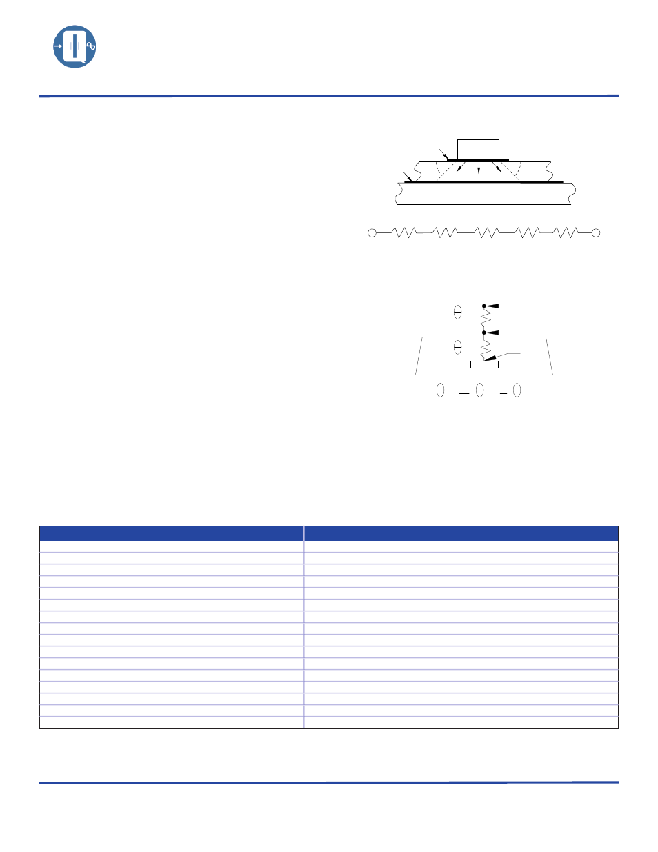
(Figure 1)
(Figure 2)
The heat transfer model in a hybrid package is described in figure 1.
Heat spreading occurs when heat flows into a material layer of
increased cross-sectional area. It is adequate to assume that spreading
occurs at a 45° angle.
The total thermal resistance is calculated by summing the thermal
resistances of each material in the thermal path between the device
and hybrid case.
RT = R1 + R2 + R3 + R4 + R5
The total thermal resistance RT (see figure 2) between the heat source
(die) to the hybrid case is the Theta Junction to Case (Theta JC)
in°C/W.
• Theta junction to case (Theta JC) for this product is 30°C/W.
• Theta case to ambient (Theta CA) for this part is 100°C/W.
• Theta Junction to ambient (Theta JA) is 130°C/W.
Maximum power dissipation PD for this package at 25°C is:
• PD(max) = (TJ (max) – TA)/Theta JA
• With TJ = 175°C (Maximum junction temperature of die)
• PD(max) = (175 – 25)/130 = 1.15W
Environmental Specifications
Q-Tech Standard Screening/QCI (MIL-PRF55310) is available for all of our Leadless Chip Carrier packages. Q-Tech can also
customize screening and test procedures to meet your specific requirements. The Leadless Chip Carrier packages are designed and
processed to exceed the following test conditions:
Environmental Test
Test Conditions
Temperature cycling
MIL-STD-883, Method 1010, Cond. B
Constant acceleration
MIL-STD-883, Method 2001, Cond. A, Y1
Seal: Fine and Gross Leak
MIL-STD-883, Method 1014, Cond. A and C
Burn-in
160 hours, 125°C with load
Aging
30 days, 70°C, ± 1.5ppm max
Vibration sinusoidal
MIL-STD-202, Method 204, Cond. D
Shock, non operating
MIL-STD-202, Method 213, Cond. I
Thermal shock, non operating
MIL-STD-202, Method 107, Cond. B
Ambient pressure, non operating
MIL-STD-202, 105, Cond. C, 5 minutes dwell time minimum
Resistance to solder heat
MIL-STD-202, Method 210, Cond. B
Moisture resistance
MIL-STD-202, Method 106
Terminal strength
MIL-STD-202, Method 211, Cond. C
Resistance to solvents
MIL-STD-202, Method 215
Solderability
MIL-STD-202, Method 208
ESD Classification
MIL-STD-883, Method 3015, Class 1HBM 0 to 1,999V
Moisture Sensitivity Level
J-STD-020, MSL=1
Please contact Q-Tech for higher shock requirements