2 connecting the hardware, 1 install the ls100m onto the test bed – SENA LS100M-SK User Manual
Page 13
13
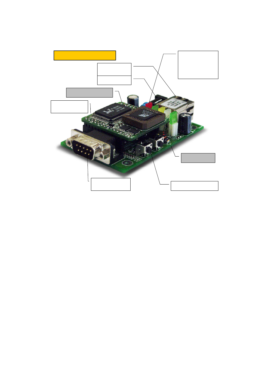
Rear side
HelloDevice LS100M
Carrier board
RS232 serial interface
(male DB9 connector)
Power jack
Ethernet interface
(RJ45 connector)
SW1: Factory Reset switch
7 LEDs:
Ethernet Rx, Tx,
Link, Collision/Act
Serial Rx/Tx
Power
Ready
HelloDevice LS100M-SK
SW2:
Console/Data switch
Figure 2-3. Picture of the HelloDevice LS100M and the LS100M-SK after the installation
2.2 Connecting the Hardware
This section describes how to install the LS100M onto the test bed and how to connect the test bed to
the serial device for the first time test.
- Install the LS100M module to the test bed
- Connect the power to the test bed
- Connect the Ethernet cable between the test bed and Ethernet hub or switch
- Connect the serial data cable between the test bed and a serial device
2.2.1 Install the LS100M onto the test bed
Plug the LS100M module onto the test bed considering the corresponding jumper pins. Keep in mind
that the direction of the triangle mark(∇) should be coincident with each other between the LS100M
and the test bed. Refer to the Figure 2-4 for the installation.