2 test bed – SENA LS100M-SK User Manual
Page 11
11
Figure 2-1. Board layout and dimension of the HelloDevice LS100M
2.1.2 Test bed
The LS100M-SK includes a test bed (carrier board) that provides serial connections to the LS100M
DIL module. The test bed contains 10-Base-T RJ45 , LEDs, a voltage regulator, a power supply circuit,
TTL to RS-232, RS232 to TTL conversion hardware, RS232 DB9 connector, a factory reset switch,
console/data switch. The test bed allows the engineers to immediately begin developing and testing
software applications for the LS100M, rather than delaying the process until the hardware interface for
their product is complete. Table 2-2 shows the pin assignment of the test bed, and Table 2-3 shows the
LED description of the board. The test bed has seven LED indicator lamps for status display. Four
lamps indicate the statuses of 10 Base-T Ethernet Rx, Tx, Collision/Link and Act. Next lamp indicates
statuses of receive and transmit of the serial port for data communication. Next two lamps indicate the
system ready status and the system power-on status.
For the installation, users will have to plug in the LS100M module to the test bed considering the
interface pin direction. Figure 2-2 is a picture representing the dimensional factors and the layout of
the test bed, whereas the Figure 2-3 is the one that shows the picture of the LS100M-SK after the
installation of the LS100M and the test bed.
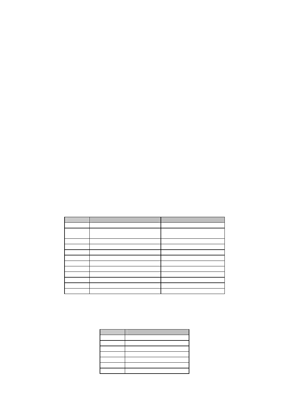
Table 2-2 Pin-out for the LS100M test bed interface
Pin NO.
JP1
JP2
1
Vcc
GND
2
Console/Data switch
(High : Data, Low : Console)
Reset(High Active)
3
Serial DSR
LED (Ethernet Tx)
4
Serial CTS
LED (Ethernet Rx)
5
Serial DTR
LED (Ethernet Link/Collision)
6
Serial RTS
Ethernet Tx-
7
Serial Rx
Ethernet Tx+
8
Serial Tx
Ethernet Rx+
9
Factory Reset switch(Low Active)
Ethernet Rx-
10
GND
Vcc
11
LED (Serial Tx)
LED (Ready )
12
LED (Serial Rx)
LED (Ethernet Act)
Table 2-3 LEDs on the test bed
LED NO.
Description
1
Ethernet Tx
2
Ethernet Rx
3
Ethernet Link/Collision
4
Power
5
Ethernet Act
6
Serial Rx/Tx (2-color)
7
Ready