4 digital i/o interface, Figure 3.4 pin assignment of i/o control connector – SENA HD1100 User Manual
Page 9
Starter Kit and User Manual for the HelloDevice 1100
6
3.4 Digital I/O Interface
The digital I/O interface of the HelloDevice 1100 is equipped with 16 input / 16 output contact points. Users can
connect switch or On/Off sensors to the input contact points, or connect LED or On/Off actuators to the output
contact points. The following table shows the voltage specifications for I/O control. The power supply for the
operation comes from the HelloDevice connectors.
Table 3.1. Voltage specifications for HelloDevice I/O operation
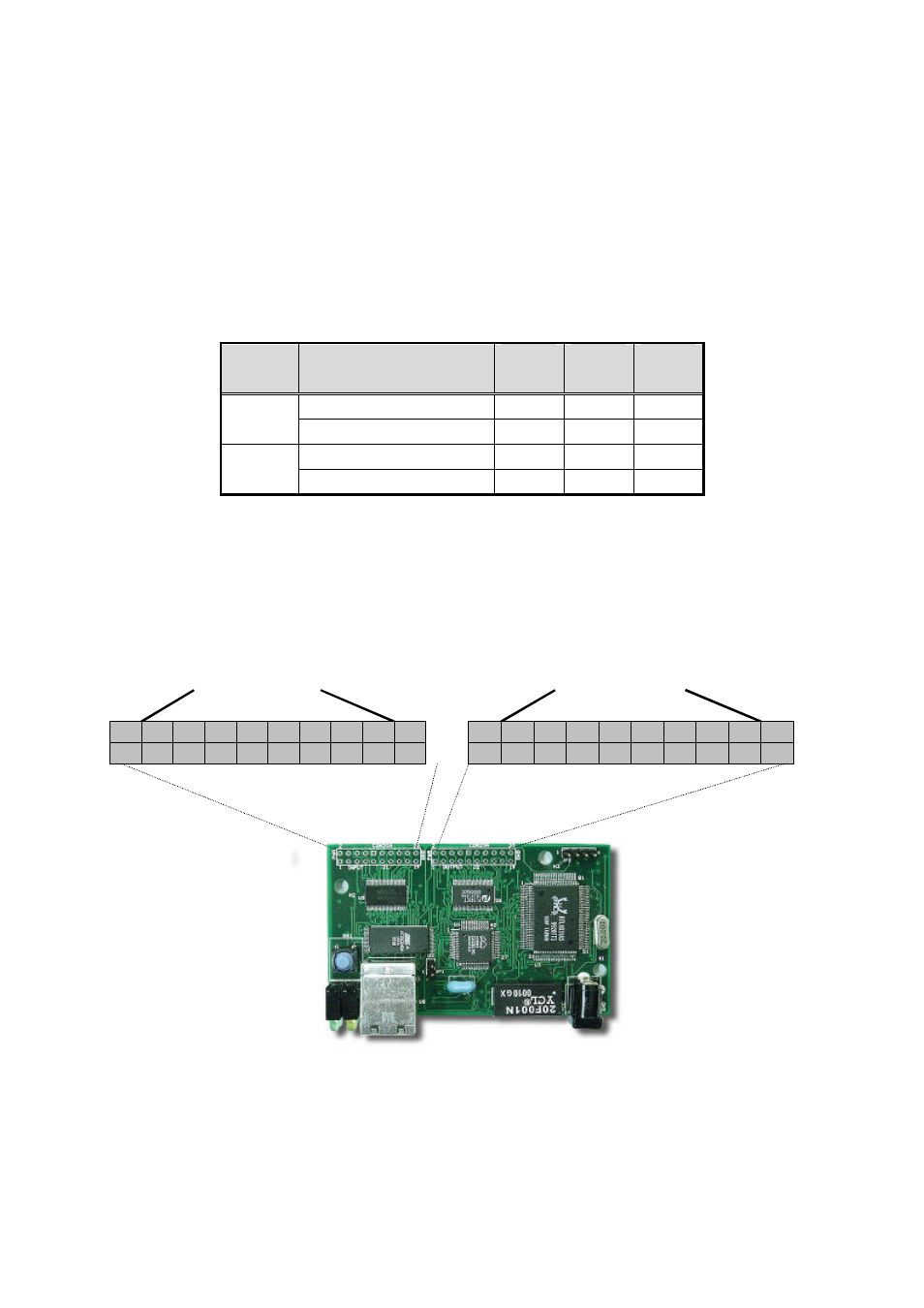
Digital I/O between the user device and the HelloDevice is performed through 2.5mm pitch, 20-pin connector J1
and J2. The Figure 3.4 shows pin assignment of the I/O connectors.
Figure 3.4 Pin assignment of I/O control connector
Control
Signal
Voltage Level
Min.
(V)
Normal
(V)
Max.
(V)
Input Hi voltage (ViH)
2
5
Input
Input Low voltage (ViL)
0
0.8
Output Hi voltage (VoH)
2.5
5
Output
Output Low voltage (VoL)
5V TTL Output Contact Point (16)
4
2
3
1
8
6
7
5
20
18
19
17
16
14
15
13
12
10
11
9
Vcc
Vcc
GND
GND
5V TTL Input Contact Point (16)
4
2
3
1
8
6
7
5
20
18
19
17
16
14
15
13
12
10
11
9
Vcc
Vcc
GND
GND