2 implementing your hardware – SENA HD1100 User Manual
Page 34
Starter Kit and User Manual for the HelloDevice 1100
31
6.2.2 Implementing your Hardware
1) Connection to the HelloDevice
The user can directly connect his device to the HelloDevice using the 20-pin connector (2.5mm pitch) instead
of connecting through the demo board. The users can access the 5V power supply from the HelloDevice
through 20-pin connector, or provide their own power supply. The state of the input or output contact points
can be initialized to run as the High Active or Low Active. The I/O contact points of the HelloDevice run at
5V TTL power, and can recognize high or low inputs depending on the hardware design, or can set the output
status as high or low depending on user design.
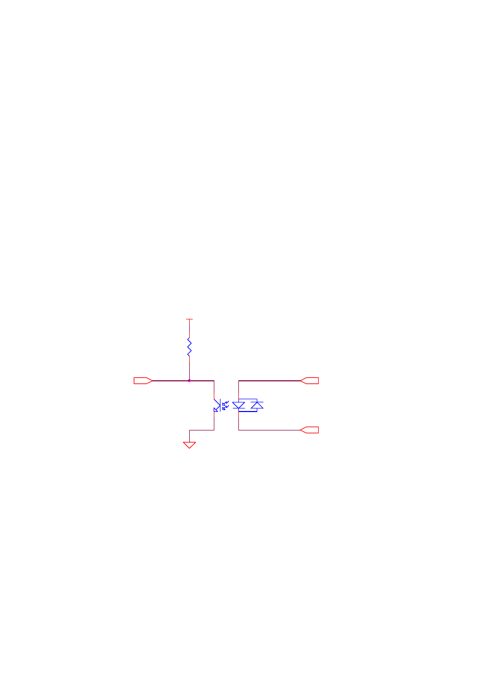
2) Input Unit Design
The user device can send high or low signal of 5V TTL level to the input interface unit of the HelloDevice
through the photocoupler. That is, when the photocoupler (PC345) connected to the input terminal of the
external device becomes an “ON” status, the input contact point unit of the HelloDevice can receive the signal
and drops from high to low.
i.
Hello Device Vcc
PC?
PC354NT
2
4
3
1
R4
R
IN
I_A
I_B
Figure 6.7. Example of input interface hardware design with the HelloDevice
3) Output Unit Design
The 5V TTL level signal generated by the HelloDevice is set to match the voltage level of the user device.
When the status of the output point is changed from high to low by connecting the photocoupler (PC817) of
the HelloDevice between Vcc and the output point, a relay can be used for on/off control of the connected
device Figure 6.8 shows an example of a circuit to use an output contact point.