Jumper block 3 (jp3) r-ls-450 operation matrix, Jumper block 3 (jp3), R-ls-450 operation matrix – Ocean Optics LS-450 User Manual
Page 17
3: R-LS-450 Rack-mount Setup and Operation
009-00000-450-02-201105
3
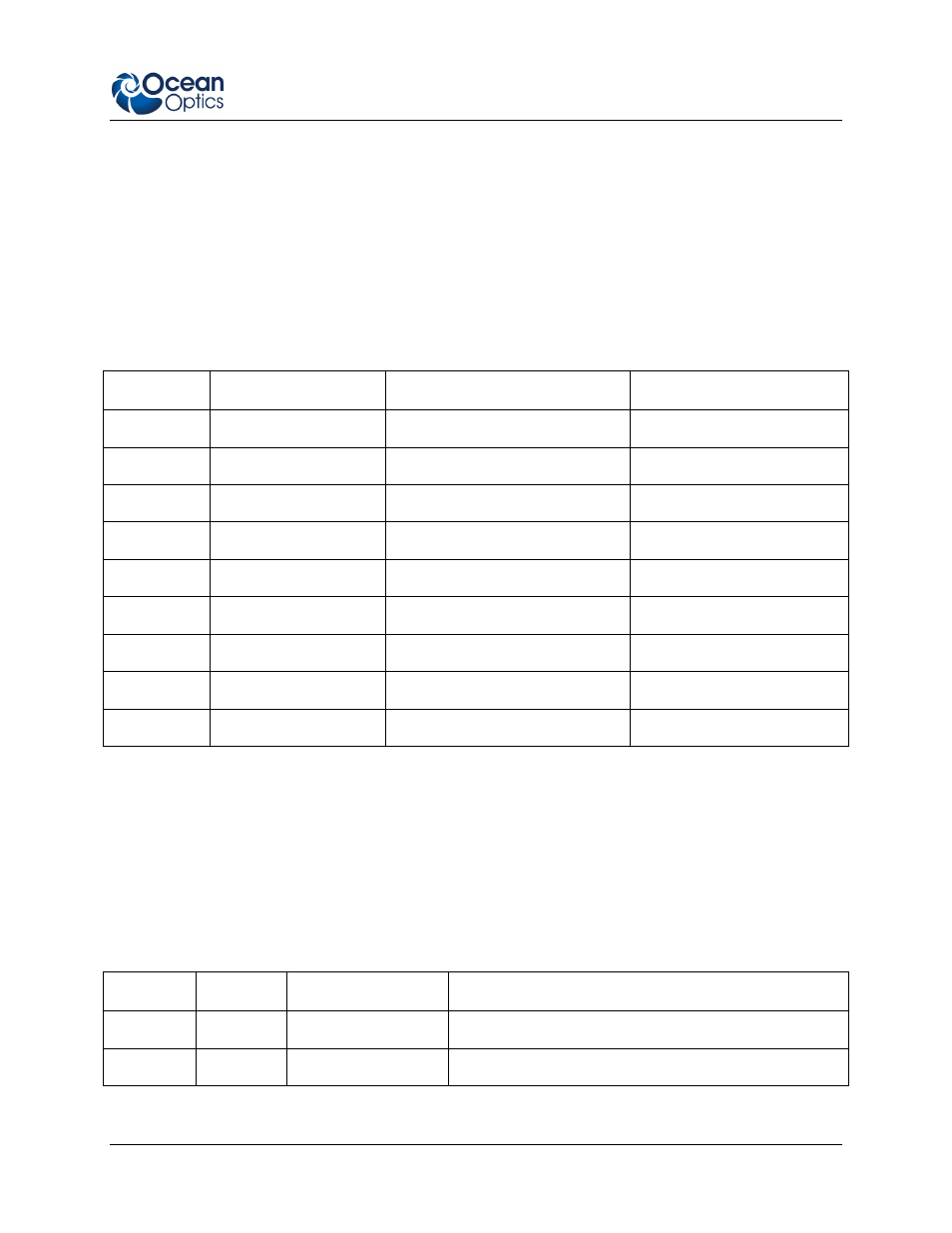
The following table contains information on the function of each set of pins in JP2.
Jumpering the CW pins makes the R-LS-450 operate continuously. This means that there is no
pulsing of the light source. Other jumper blocks must be configured correctly for this setting to
work properly.
Jumpering sets 2
16
, 2
15
, 2
14
, 2
13
, 2
12
, 2
11
, and 2
10
controls the pulse rate per second of the R-LS-
450, depending on the A/D converter you are using to interface to the spectrometer (see the table
below for pulse rates).
Jumpering the CS pins controls the pulse rate via the spectrometer’s Continuous Strobe Setting in
OOIBase32 software (see the Using JP3 on the S2000 section that follows for more information).
JP2 Pins
Function
ADC1000 Frequency (Hz)
ADC2000-PCI Frequency (Hz)
CW
Continuous mode
0
0
2
16
Divide by 2
16
15.2
30.4
2
15
Divide by 2
15
30.4
60.8
2
14
Divide by 2
14
60.8
122.0
2
13
Divide by 2
13
122.0
244.0
2
12
Divide by 2
12
244.0
488.0
2
11
Divide by 2
11
488.0
976.0
2
10
Divide by 2
10
976.0
1952.0
CS
Continuous Strobe
Software-controlled
Software-controlled
Jumper Block 3 (JP3)
JP3 consists of two sets of pins. The jumper position determines the source of power control (manual or
remote) for the R-LS-450. Jumping the Remote pins allows you to control the R-LS-450 through the
software (if other jumper blocks are configured correctly).
R-LS-450 Operation Matrix
Use the following operation matrix to help you determine the correct jumper settings:
S1 Switch
JP1
JP3
LED Status
Off
No jumper
No jumper
Off
CW
No jumper
No jumper
Continuously On