Optical adjustments, Packages for specific applications – Ocean Optics CUV-TLC-50F User Manual
Page 14
2: Operation
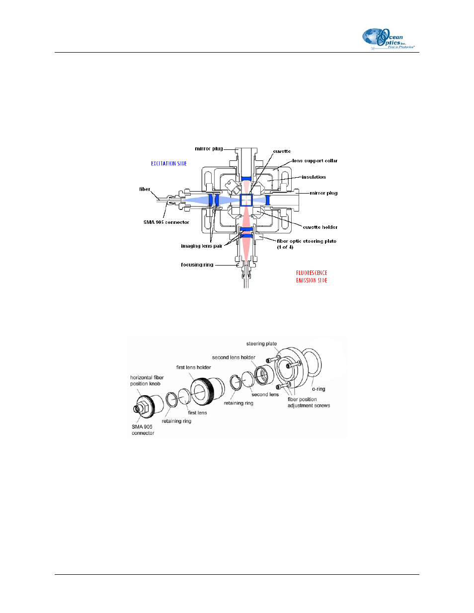
Typical Configuration for Fluorescence Measurements
To measure fluorescence, Imaging Lens systems are placed at 90 degrees to each other. The first lens
system focuses the light as a small image inside the cuvette Emitted light from this small illuminated
volume is then focused at a right angle onto the second fiber. Mirrors can be mounted opposite each lens
system, nearly quadrupling measured light intensities.
CUV-TLC-50F Typical Configuration for Fluorescence Measurements
The following figure shows the components of an imaging lens system.
Components of an Imaging Lens System
Optical Adjustments
The fiber position adjustment screws use the steering plate to compress a soft o-ring. They may be used to
wobble the end of the fiber horizontally and vertically about its position and can substantially enhance
optical throughput. Take care not to over compress the o-ring. Alternatively, no adjustment is possible if
the steering plate is not in contact with the o-ring. Screwing in or unscrewing the horizontal fiber position
knob may vary the distance between the end of the fiber and the center of the cuvette.
8
000-30000-000-02-0205