Spectral output: ls-1 and r-ls-1 – Ocean Optics LS-1 Series User Manual
Page 10
LS-1 Installation and Operation Instructions
10
009-00000-STD-01-201010
The light on the R-LS-1 can be toggled on and off through a TTL signal. This signal is supplied by the
spectrometer operating software through the PC to Pin 8 on H2. However, in order for software to
control the on/off function of the R-LS-1, the JP1 jumper must be closed.
Note
When using a Rev. D S2000 Spectrometer, you must remove the jumper from JP1 on
the R-LS-1. In this state, you can only operate the R-LS-1 via the power switch on the
light source.
JP2 is a power jumper that allows multiple stacked light sources to use a single power supply by
running power to each unit via H2 (alternate Voltage).
Note
JP1 is the strobe enable jumper (S0). This jumper must be closed to enable software
on/off functionality.
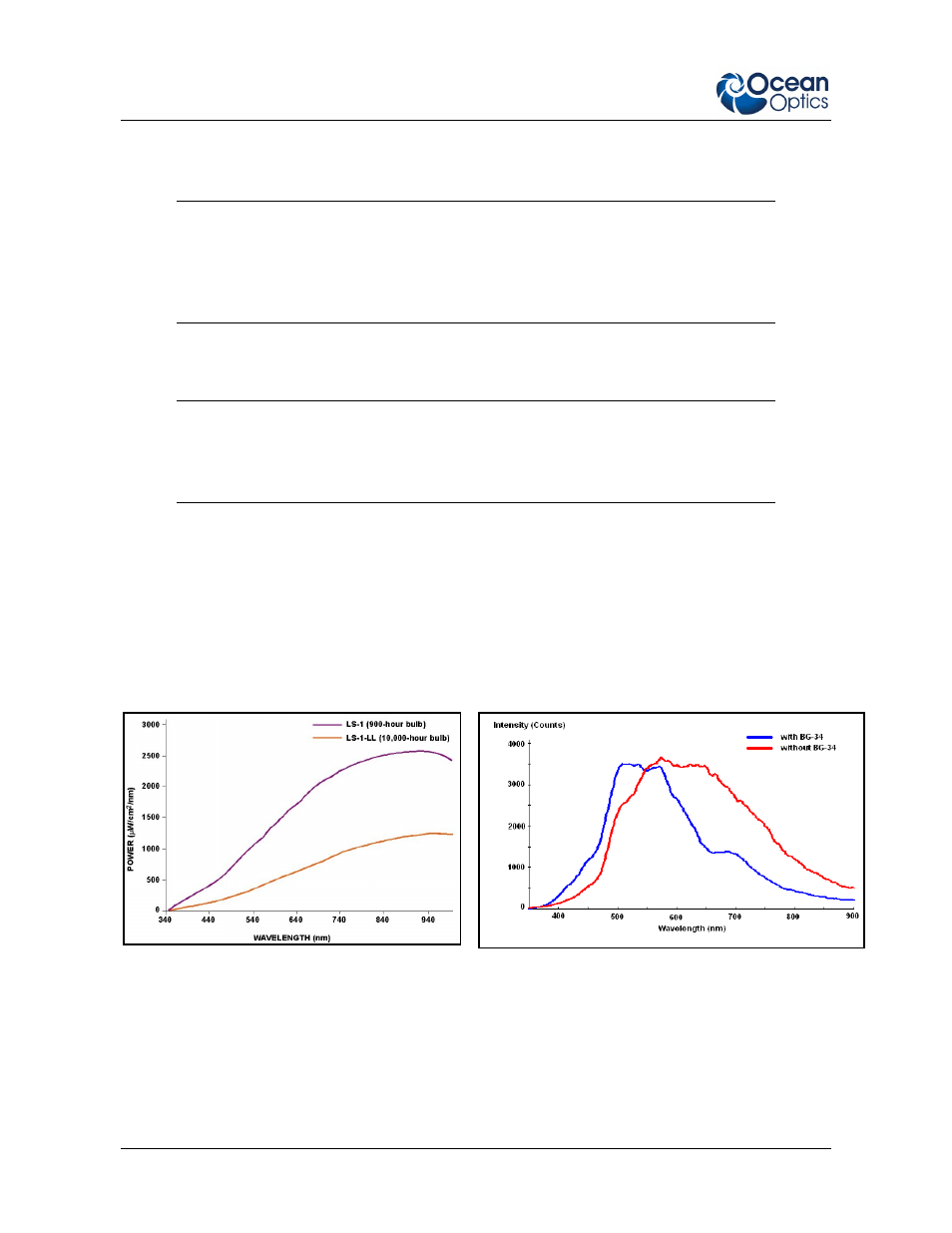
Spectral Output: LS-1 and R-LS-1
The graph on the left represents normalized blackbody curves for tungsten halogen light sources with
2800K and 3100K color temperatures. The observed spectral output of the LS-1 will vary due to bulb
type, spectrometer configuration, sampling optics in use, and inherent fluctuations in LS-1 output.
The graph on the right represents the Scope mode signal from the LS-1 with and without the BG-34
filter.
Normalized blackbody curves for 2800K and 3100K
color temperatures
Comparison of typical LS-1 Scope mode signal with and
without BG-34 filter