Accessory connector pinout diagram – Ocean Optics Torus Operating Instructions User Manual
Page 27
C: Specifications
270-00000-000- 02-201208
21
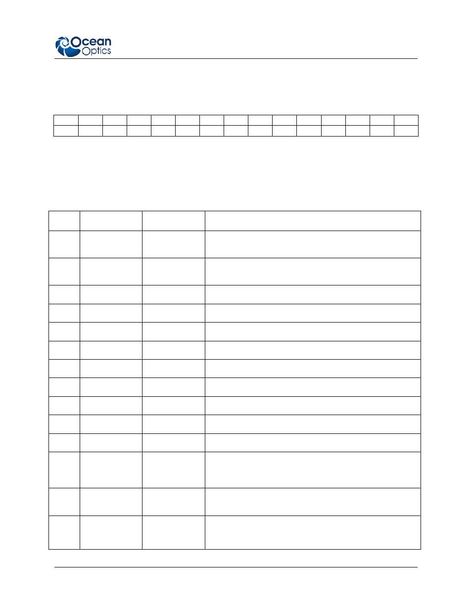
Accessory Connector Pinout Diagram
When facing the 30-pin Accessory Connector on the front of the vertical wall of the Torus, pin numbering
is as follows:
2
4
6
8
10
12
14
16
18
20
22
24
26
28
30
1
3
5
7
9
11
13
15
17
19
21
23
25
27
29
30-Pin Accessory Connector Pinout Diagram
Accessory Connector – Pin Definitions and Descriptions
The following table contains information regarding the function of each pin in the Torus’s 30-Pin
Accessory Connector:
Pin #
Function
Input/Output
Description
1
RS232 Rx
Input
RS232 receive signal – Communicates with a computer over
DB9 Pin 1
2
RS232 Tx
Output
RS232 transmit signal – Communicates with a computer
over DB9 Pin 2
3
GPIO (2)
Input/Output
Reserved
4
V5-SW
N/A
5
Ground
Input/Output
Ground
6
I2C SL
Input/Output
I2C clock signal for communication to other I2C peripherals
7
GPIO (0)
Input/Output
Base clock
8
I2C SDA
Input/Output
9
GPIO (1)
Input/Output
Master clock
10
Ext. Trigger In
Input
TTL input trigger signal
11
GPIO (3)
Input/Output
Integration clock
12
VCC, VUSB or
5Vin
Input or Output
Input power pin for Torus – When operating via USB, this pin
can power other peripherals – Ensure that peripherals
comply with USB specifications
13
MOSI
Output
The SPI Master Out Slave In (MOSI) signal for
communications to other SPI peripherals
14
VCC, VUSB or
5Vin
Input or Output
Input power pin for Torus – When operating via USB, this pin can
power other peripherals – Ensure that peripherals comply with USB
specifications