2 controls, indicators and connectors – Crown Audio PIP-Lite Module User Manual
Page 11
page 11
Reference Manual
Networked PIP Series
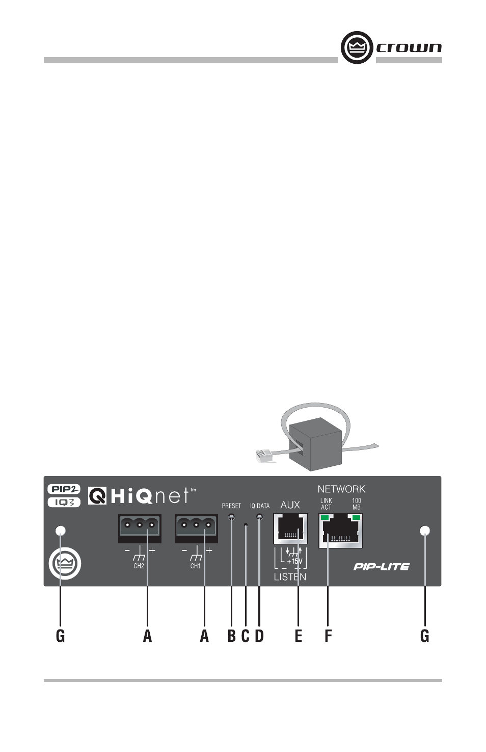
2 Controls, Indicators and Connectors
Figure 2.1 PIP-Lite Front Panel Controls, Indicators and Connectors
(Note: Actual Product Artwork May Vary Slightly)
ANALOG AUDIO INPUTS
TCP / IQ
A. Balanced Audio Input Connectors
3-pin removable barrier-strip connectors, one per channel.
B. Preset Indicator
Signals the number of the current preset, if active, by flashing a series of flashes equal to
the current preset number. See Section 4.1.2.
C. Reset/Preset Switch
Used to change presets, restore settings to factory default or restore all the presets to the
factory defaults. During operations of the switch, the Data indicator flashes as an aid to
the user. See Section 4.1.11.
D. Data Indicator
Flashes when the PIP-Lite receives a valid command that is addressed to the PIP-Lite.
See Section 4.1.1.
E. AUX Connector
AUX input, AUX output, and Listen Bus. See Section 6.1.
F. Network Connector
The network connector is a standard RJ-45 connector that allows the PIP-Lite to connect
to an Ethernet network. Connection is made using a standard Category 5 or better cable
to a network switch port. For compliance with emission regulations, the supplied ferrite
core must be placed on the CAT5 cable, with the cable making two passes through the
core as shown in Figure 2.2. The Link Activity LED indicates data activity on the network
line. The 100 MB LED indicates that the data is at 100 Megabits. See Section 4.1.3.
G. Mounting Holes
2.1 PIP-Lite
Figure 2.2 Pass the CAT5
Cable Twice Through the
Supplied Ferrite Core