Page 9 – Crown Audio PIP-USP4 Module User Manual
Page 9
Networked PIP Series
Reference Manual
page 9
Connect the PIP-USP4-CN module to the amplifi er
(Note: PIP-USP4-CN only works with CTs 2-Channel
models).
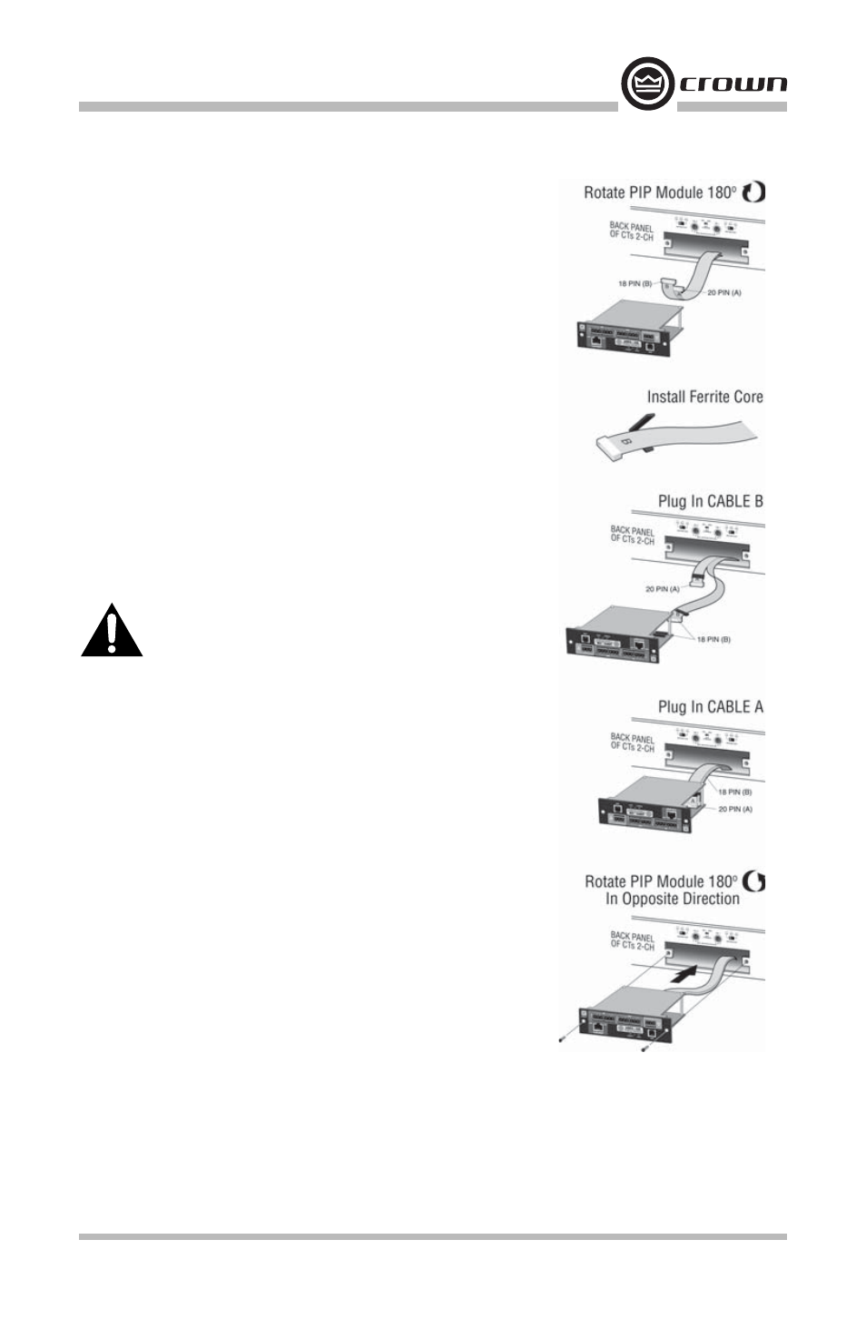
1. Turn the PIP module upside down so the ribbon
cable connectors located along the back edge on the
underside of the module can be clearly seen.
2. Add the supplied ribbon cable ferrite core to the end
of the (B) cable.
3. Attach the ribbon cables from the amplifi er to the
ribbon-cable connectors. The 20 pin cable (A) should
connect to the connector further inside and away
from the corner (AJ9) and the 18 pin cable should
connect to the one closest to the corner (BJ5). Start
by connecting cable B.
Important: Be careful when attaching the ribbon cable
to the connector. Don’t pull cables out if they are short.
Applying pressure to an improperly seated connector could
cause the keying tabs, which ensure proper pin alignment,
to break. Connecting the ribbon cables with improper pin
alignment will likely result in damage to the PIP module.
4. Set amplifi er sensitivity to 26dB, by placing both
sensitivity switches in the center position.
5. The Bridge-Mono Mode is set via software, leave the
Mode switch in Dual and set the attenuator knobs to
full clockwise, wide open, for all the features of the
USP4 to function correctly.
Mount the PIP module in the amplifi er
1. With both cables fi rmly attached, turn the PIP to an
upright position. Verify that the cables run untwisted
between the amplifi er and the PIP module. For best
fi t, bend the cables up and roll in the cores between
the two circuit boards of the PIP module.
2. Insert the PIP module into the amplifi er while taking
care not to crimp, pinch or stretch the ribbon cables.
3. Fasten the PIP module to the amplifi er rear panel with
the two supplied mounting screws. Be sure to use the
supplied star-washers for a good ground connection.