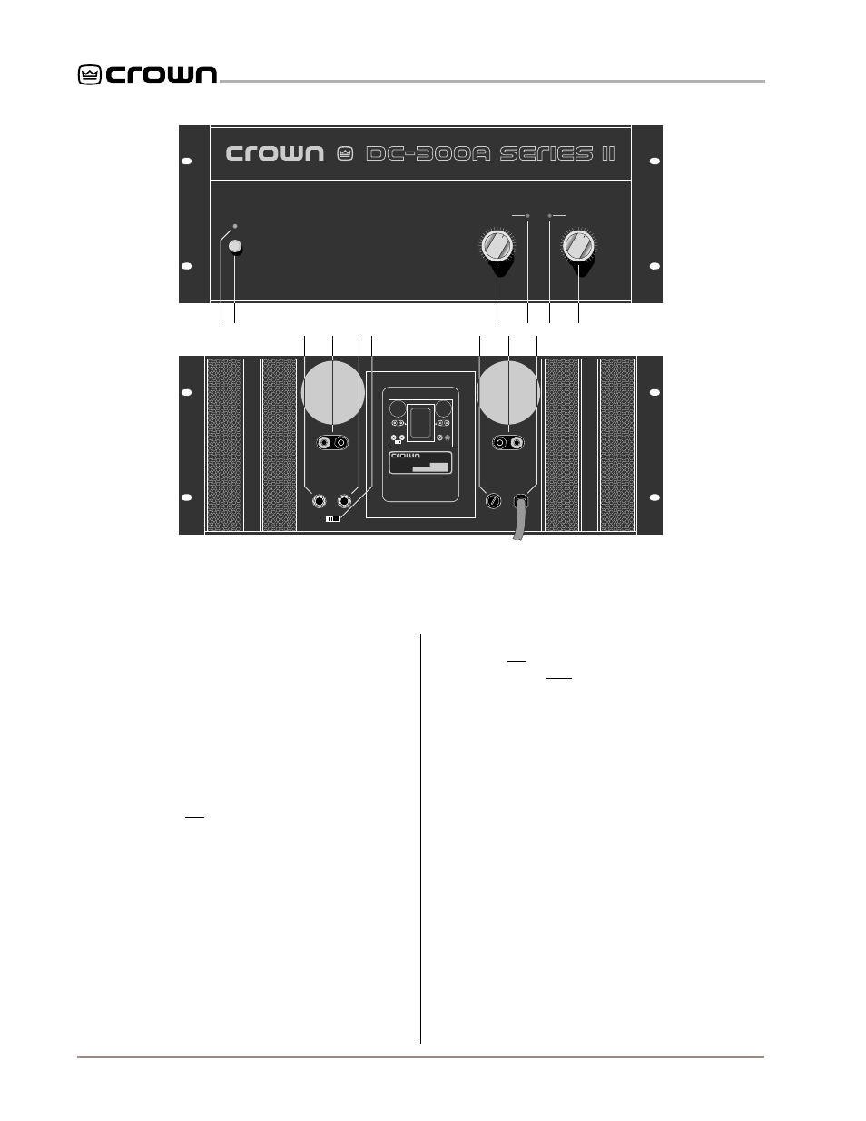
2 facilities, A. power indicator, B. power switch – Crown Audio DC-300AII User Manual
Page 8: C. input jacks, D. output jacks, E. dual-mono switch, F. fuse holder, G. level controls, H. power cord, Indicators
DC-300A II
Power Amplifier
Page 8
POWER
CHANNEL 1
CHANNEL 2
I0C
0
10
20
40
50
30
0
10
20
40
50
30
®
INTERNATIONAL, INC.
ELECTRONIC EQUIPMENT
ELKHART, IN 46517
MADE IN U.S.A.
SERIAL NUMBER
0000
000000
OUTPUT
CHANNEL 2
OUTPUT
CHANNEL 1
2 INPUT 1
LINE
DUAL MONO
FUSE AC
A
B
D
G
H
H
G
F
C
C
E
D
I
2 Facilities
A. Power Indicator
This indicator glows when the amplifier is turned on.
B. Power Switch
This push button turns the DC-300A II on and off. The
unit has no turn-on delay and minimal thumps. Always
turn the amplifier on last so the turn-on transients of
other components will not be amplified.
C. Input Jacks
An unbalanced ¼ inch phone jack is used for input to
each channel. Do not use the channel 2 input in Bridge-
Mono mode.
D. Output Jacks
5-way binding posts provide output from each chan-
nel. Use banana plugs, spade lugs or bare wire to con-
nect loudspeaker cables. In Bridge-Mono mode,
connect the positive (+) loudspeaker terminal to the
positive (+) channel 1 output and the negative (–) loud-
speaker terminal to the positive (+) channel 2 output.
E. Dual-Mono Switch
Facing the back of the amplifier, slide this switch to the
left for Dual (stereo) mode and to the right for Bridge-
Fig. 2.1 Facilities
Mono mode. In Bridge-Mono mode, the channel 2 in-
put should not be used, its level control should be
turned down and only balanced (ungrounded) loads
should be connected to the output (see section 3.3.1).
F. Fuse Holder
The AC line is safely fused. Use a 10 amp, 250 volt,
type AB fuse for 100 and 120 VAC operation, or a
5 amp, 250 volt, type MTH fuse for 200, 220 and
240 VAC units (see Sections 3.3.5 and 4.5).
G. Level Controls
The output level of each channel is adjusted with these
controls. Turn the channel 2 level control down com-
pletely when using Bridge-Mono mode.
H. Power Cord
The unit has a grounded, three wire AC cord and plug.
I.
IOC
Indicators
The red Input/Output Comparator (
IOC) indicators pro-
vide
proof of distortion-free performance. Normally off,
they flash in the rare event that the output waveform
differs from the input by 0.05% or more.