5 fuse replacement, Fig. 5.1 circuit block diagram – Crown Audio DC-300AII User Manual
Page 16
DC-300A II
Power Amplifier
Page 16
The input stages are protected from overload by series
resistors. The unit also features a controlled slew rate
and the JTS limiter that protect the amplifier from high-
frequency blowups.
A thermal switch is mounted on each heat sink to pro-
tect your amplifier against overheating. If either heat
sink becomes too hot, the AC mains power will be in-
terrupted until the temperature falls to a safe level and
the unit resets itself. If the unit overheats, it will not pro-
duce any output and it will be very warm to touch.
4.5 Fuse Replacement
An AC line fuse is located beside the power cord on
the back panel of the amplifier. To replace the fuse,
turn off the power switch and disconnect the power
plug from the AC mains. Unscrew the cap of the fuse
holder and remove the fuse.
CAUTION: The fuse holder has power even when
the power switch is turned off. Always disconnect
AC power before replacing fuses.
Replace the fuse with a 10 amp, 250 volt, type AB fuse
for units operating with an AC mains voltage less than
200 volts, or a 5 amp, 250 volt, type MTH fuse for units
operating with an AC mains voltage of 200 volts or
more. Reassemble in reverse order.
WARNING: Never replace the original fuse with one
rated for higher current (amperage).
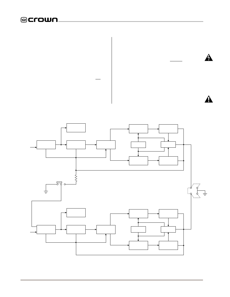
Fig. 5.1 Circuit Block Diagram
INPUT
AMP
INPUT
OUTPUT
COMPARATOR
SIGNAL
TRANSLATOR
LAST
VOLTAGE
AMP
POSITIVE
DRIVER
STAGE
BIAS
SERVO
NEGATIVE
DRIVER
STAGE
POSITIVE
OUTPUT
STAGE
PROTECTION
CIRCUIT
NEGATIVE
OUTPUT
STAGE
CHANNEL 1
INPUT
–
+
INPUT
AMP
INPUT
OUTPUT
COMPARATOR
SIGNAL
TRANSLATOR
LAST
VOLTAGE
AMP
POSITIVE
DRIVER
STAGE
BIAS
SERVO
NEGATIVE
DRIVER
STAGE
POSITIVE
OUTPUT
STAGE
PROTECTION
CIRCUIT
NEGATIVE
OUTPUT
STAGE
CHANNEL 2
INPUT
–
+
DUAL
MONO
10 K
MONO
CHANNEL 1
OUTPUT
CHANNEL 2
OUTPUT