Use good connectors – Crown Audio DC-300AII User Manual
Page 13
DC-300A II
Power Amplifier
Page 13
filters described in Section 3.3.2.
5. Install the input wiring according to the instruc-
tions in Section 3.3.2.
Another problem to avoid is the presence of
large sub-
sonic currents
when primarily inductive loads are
used. Examples of inductive loads are 70 volt step-up
transformers and electrostatic loudspeakers.
Inductive loads can appear as a “short” at low frequen-
cies, causing the amplifier to produce large low-fre-
quency currents and unnecessarily activate its
protection circuitry. Always take the precaution of in-
stalling a high-pass filter on the amplifier inputs when a
predominantly inductive load is used. A three pole (18
dB per octave) filter with a –3 dB frequency of 50 Hz is
recommended. (Depending on the system, it may be
preferable to use a filter with a higher –3 dB frequency.)
Such a filter can eliminate the subsonic frequency
problems mentioned in Section 3.3.2.
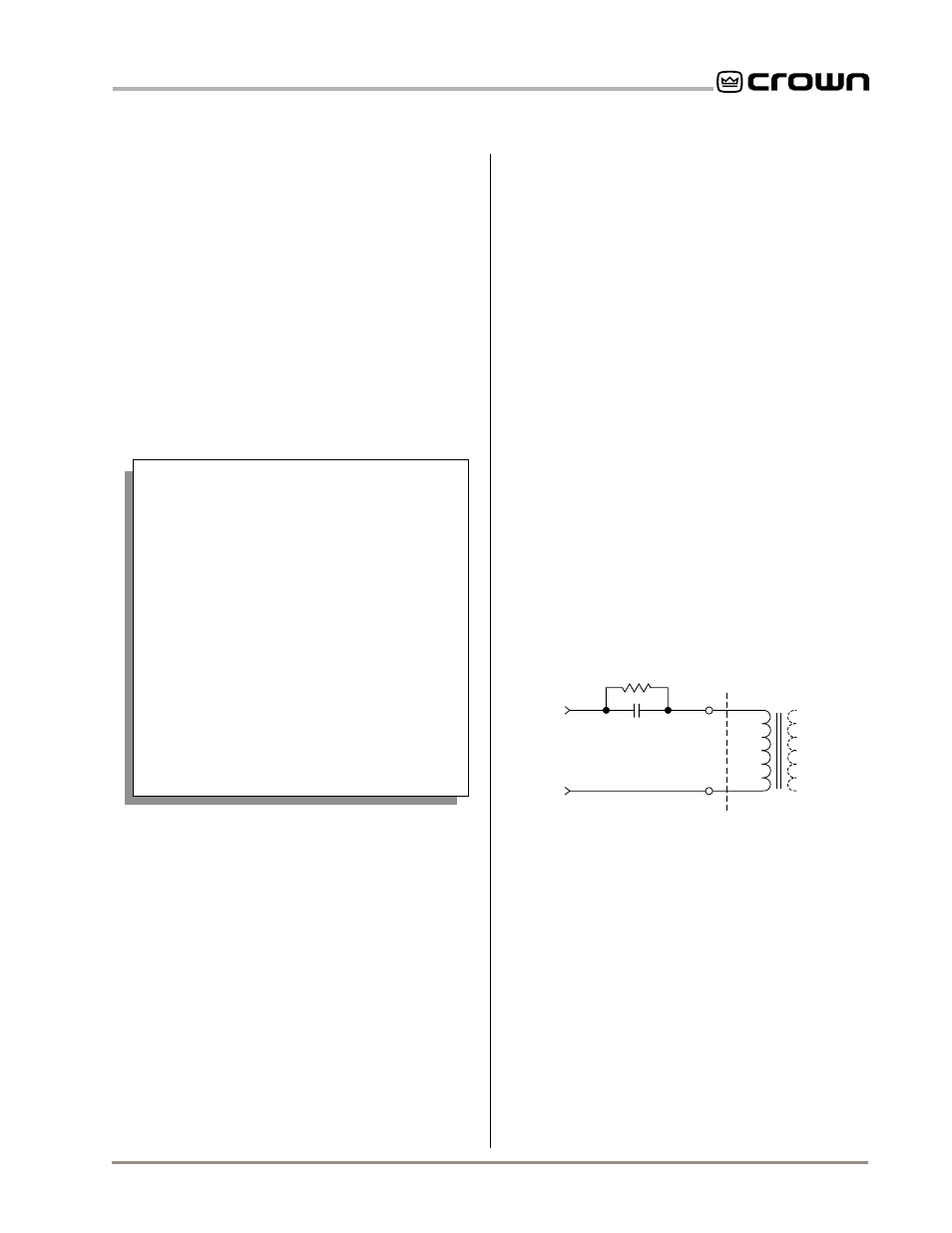
Another way to prevent the amplifier from activating its
protection systems early and protect inductive loads
from large low-frequency currents is to connect a 590
to 708 µF nonpolarized capacitor and a 4 ohm, 20 watt
resistor at the output of the amplifier in series with the
positive (+) lead of the transformer. This is depicted in
Figure 3.8.
Note: The components shown in Figure 3.8 are com-
monly available from most electronic supply stores.
3.3.4 Additional Load Protection
Because your amplifier can generate enormous power,
you may want to protect loudspeakers or other sensi-
tive loads from excessive power that could result in
damage. A common way to do this is to put a fuse in
series with the load. This may be accomplished by us-
ing a single fuse to protect the entire system, or by
fusing each driver.
Fuses help prevent damage due to prolonged over-
load, but provide essentially no protection against
damage from large transients. To minimize this prob-
lem, use high-speed instrument fuses such as the
4-ohm, 20-watt
Resistor
590 to 708
µ
f Capacitor
120 VAC, N.P.
+
–
Inductive
Load
+
–
From
Amplifier
Output
Fig. 3.8 Inductive Load (Transformer) Network
3. Draw a line through the two points with a pencil, and continue until
it intersects the “Source Resistance” line.
4. On the “2-Cond. Cable” line, mark the length of cable run.
5. Draw a pencil line from the mark on the “Source Resistance” line
through the mark on the “2-Cond. Cable” line, and on to intersect
the “Annealed Copper Wire” line.
6. The required wire gauge for the selected wire length and
damping factor is the value on the “Annealed Copper Wire” line.
Note: Wire size increases as the AWG gets smaller.
7. If the size of the cable exceeds what you want to use, (1) find a
way to use shorter cables, (2) settle for a lower damping factor, or
(3) use more than one cable for each line. Options 1 and 2 will
require the substitution of new values for cable length or damping
factor in the nomograph. For option 3, estimate the effective wire
gauge by subtracting 3 from the apparent wire gauge every time
the number of conductors of equal gauge is doubled. So, if #10
wire is too large, two #13 wires can be substituted, or four #16
wires can be used for the same effect.
Use Good Connectors
1. To prevent possible short circuits, do not
use loudspeaker cables with exposed
male connectors.
2. Do not use connectors that might acciden-
tally tie two channels together when mak-
ing or breaking connections, such as a
standard three wire stereo phone plug.
3. Never use connectors that can be plugged
into an AC power receptacle.
4. Avoid connectors with low current-carrying
capacity.
5. Do not use connectors with any tendency
to short.
SOLVING OUTPUT PROBLEMS
Sometimes
high frequency oscillations
occur which
can cause your amplifier to prematurely activate its pro-
tection circuitry, resulting in inefficient operation. The
effects of this problem are similar to the effects of the
RF problem described in Section 3.3.2. To prevent high
frequency oscillations:
1. Lace loudspeaker cables together to minimize
the chance of them acting like an antenna to
transmit or receive high frequencies that can
cause oscillation.
2. Keep the speaker cables well separated from
input cables.
3. Never connect the amplifier’s input and output
grounds together.
4. Install a low-pass filter on each input like the RF