7 internal settings – Crown Audio DC-300AII User Manual
Page 23
DC-300A II
Power Amplifier
Page 23
7 Internal Settings
From the factory, your amplifier is configured for an in-
put sensitivity of 26 dB gain. For the DC-300A II, this
setting requires an input signal of 1.75 volts (±2%) to
drive the amplifier to full output. You may optionally con-
figure the unit for an input sensitivity of 0.775 volts (0
dBm) for full rated output power. To change your
amplifier’s input sensitivity to 0.775 volts, the chassis of
the unit must be opened.
WARNING: Risk of electric shock! Turn off the am-
plifier and disconnect its power cord from the AC
mains before opening the amplifier chassis.
CAUTION: Only a qualified technician should at-
tempt to change the amplifier’s internal settings.
7.1 26 dB Gain vs. 0.775 V Input Sensitivity
For most applications, the amplifier’s default setting of
26 dB gain will be ideal. At 26 dB gain, full output is
achieved with an input signal of 1.75 volts. But some
systems require their gain structures to be calculated
based on a 0.775 volt sensitivity, while others cannot
deliver the voltage required to achieve full output. In
these situations, your amplifier’s 0.775 volt input sensi-
tivity setting offers a solution. A Crown Service Center
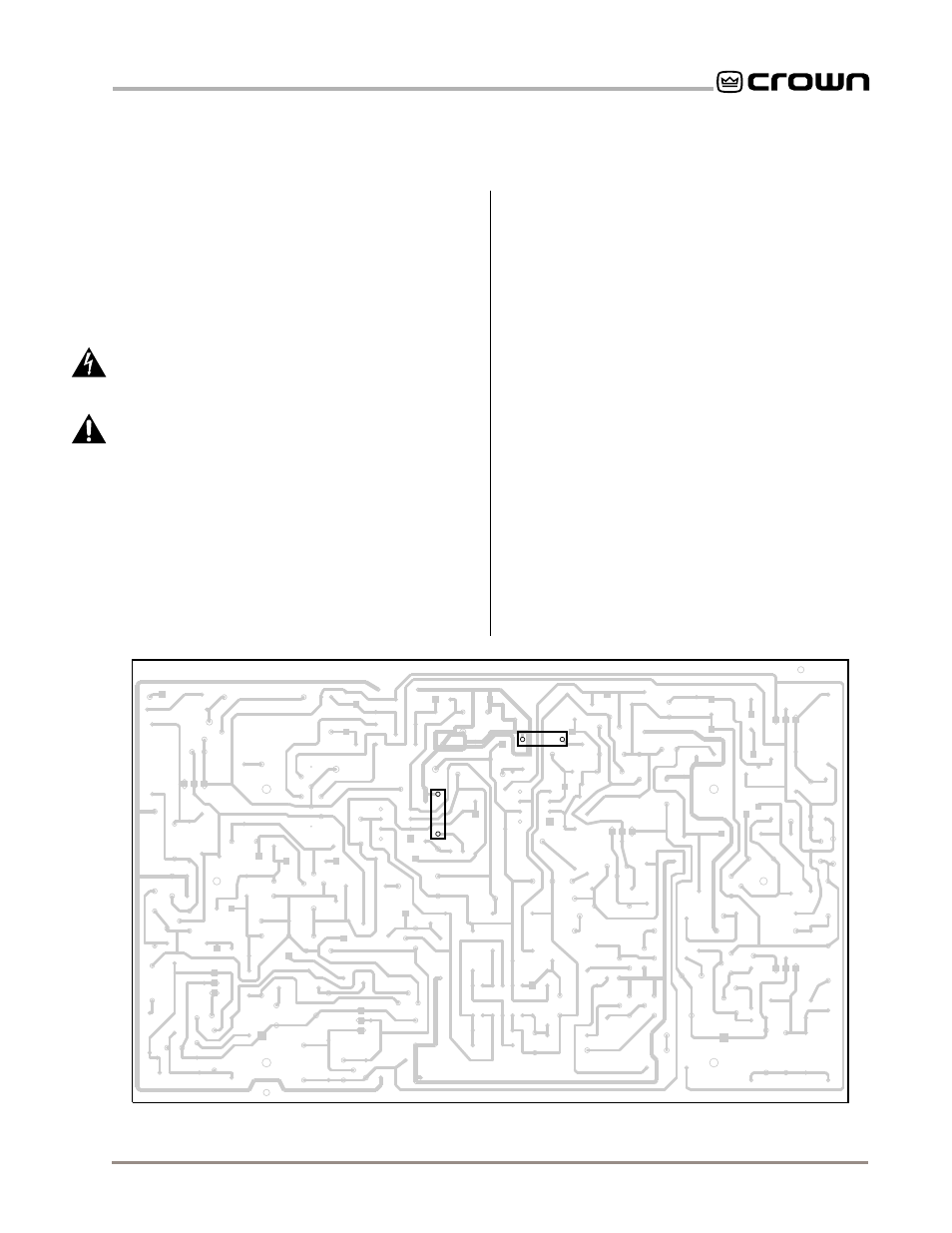
Fig. 7.1 Main Circuit Board (Component Side) and
Input Sensitivity Jumper Locations
H1
H2
H3
H4
C6
C7
C8
C200
C203
C205
C206
C208
C209
C210
C211
C212
C213
C214
C218
C219
C220
C221
C100
C103
C105
C106
C108
C109
C110
C111
C112
C113
C114
C118
C119
C120
C121
L200
L202
L100
L102
Q200
Q201
Q202
Q203
Q204
Q205
Q206
Q207
Q219
Q220
Q221
Q100
Q101
Q102
Q103
Q104
Q105
Q106
Q107
Q119
Q120
Q121
X17
X14
X16
X24
X26
X27
R1
R2
R3
R4
R8
R22
R24
R25
R26
R201
R202
R205
R206
R209
R210
R212
R213
R214
R215
R216
R217
R218
R219
R220
R221
R222
R223
R224
R225
R226
R227
R228
R229
R230
R246
R247
R250
R251
R253
R254
R256
R252
R152
R101
R102
R105
R106
R109
R110
R112
R113
R114
R115
R116
R117
R118
R119
R120
R121
R122
R123
R124
R125
R126
R127
R128
R129
R130
R146
R147
R150
R151
R153
R154
R156
W11
W12
W15
W16
W17
W18
W21
W22
W23
W24
W1
W2
W13
W14
W3
W4
W5
W6
W19
W20
W7
W8
W9
W10
W26
W27
W28
W29
W31
W30
W32
Z1
Z4
Z5
Z6
Z7
H5
H6
H10
H11
H9
Z99
R10
R157
R158
R158
R257
R258
Z10
C4
C5
D1
D2
D3
D4
D5
D7
D200
D201
D202
D203
D204
D205
D206
D207
D208
D212
D213
D100
D101
D102
D103
D104
D105
D106
D107
D108
D112
D113
U1
U200
U100
or a technician in the field can activate the setting with-
out voiding the warranty.
7.2 Changing the Input Sensitivity to 0.775 V
Before undertaking this procedure, please read all of
Section 7.1 to help determine whether you need to al-
ter the amplifier’s input sensitivity.
1. Turn the amplifier off and disconnect it from the
AC mains.
2. Place the amplifier upside down on a flat sur-
face. Remove the front panel by unscrewing the
eight phillips screws along the top and bottom
of the front panel and the four phillips screws
behind the rack ears. Pull the front panel
straight out from the unit.
3. Remove the four phillips screws that hold the
main circuit board to its shield plate. It will hinge
forward from the bottom to expose both sides.
4. Solder #22 jumper wires at the locations labeled
R158 and R258 on the main circuit board (see
Figure 7.1).
5. Reassemble in reverse order of disassembly.