Fig. 3.5 unbalanced rfi filters – Crown Audio DC-300AII User Manual
Page 11
DC-300A II
Power Amplifier
Page 11
outputs will receive the channel 1 input. The channel 2
output is inverted so it can be bridged with channel 1.
There are two different ways to connect Bridge-Mono
wiring. The most common method is to connect the
positive (+) output of channel 1 to the positive (+) loud-
speaker lead, and the positive (+) output of channel 2
to the negative (–) loudspeaker lead (see Figure 3.2).
The negative amplifier outputs are not used.
In Bridge-Mono mode, it is also possible to connect a
loudspeaker to each output channel, however, the out-
put of channel 2 is inverted. To compensate for this,
you can invert the polarity of the channel 2 output wir-
ing. First, connect a loudspeaker to channel 1 as you
would normally. Then, connect a loudspeaker to chan-
nel 2 so its positive (+) output goes to the negative (–)
loudspeaker terminal, and negative (–) output goes to
the positive (+) loudspeaker terminal.
CAUTION: Only connect balanced loads to a bridge-
mono output. Output lines must be isolated from
ground or severe oscillations may occur.
3.3.2 Input Connection
The unbalanced ¼ inch phone inputs have a typical
impedance of 25 K ohms. They accept the line level
output from most devices. Figure 3.3 shows how to
properly wire both balanced and unbalanced lines.
27 f
µ
1 f
µ
.05 f
.2 f
µ
µ
0.1 Hz
1 Hz
10 Hz
100 Hz
1 kHz
dB
0
–5
–10
–15
Frequency
Fig. 3.4 Subsonic Filter Capacitors
Fig. 3.6 Balanced RFI Filters
Fig. 3.3 Input Wiring
SOLVING INPUT PROBLEMS
Sometimes large
subsonic
(subaudible)
frequencies
are present in the input signal. These can damage
loudspeakers by overloading or overheating them. To
attenuate such frequencies, place a capacitor in se-
ries with the input signal line. The graph in Figure 3.4
shows some possible capacitor values and how they
affect frequency response. Use only a low-leakage pa-
per, mylar or tantalum capacitor.
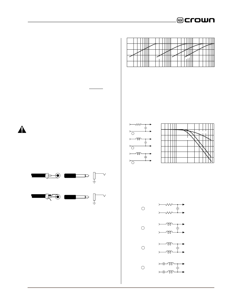
Another problem to avoid is the presence of large lev-
els of
radio frequencies
or RF in the input signal. Al-
though high RF levels may not pose a threat to the
amplifier, they can burn out tweeters or other loads that
are sensitive to high frequencies. Extremely high RF
levels can also cause your amplifier to prematurely ac-
tivate its protection circuitry, resulting in inefficient op-
eration. RF can be introduced into a signal by local
radio stations and from the bias signal of many tape
recorders. To prevent this from happening, place an
appropriate low-pass filter on the input(s). Some ex-
amples are shown below for unbalanced wiring.
4 kHz
10 kHz
40 kHz
100 kHz
Frequency
dB
0
–10
–20
A
B
C
6 dB/octave
12 dB/octave
To
Amp
GND
To
Amp
GND
To
Amp
GND
Source
1.8 K ohm
.003
f
µ
.015
f
µ
.018
f
µ
3.9 mH
5 mH
600 ohm
Source
R
600 ohm
Source
R
A
C
B
Note: A low source impedance (R) can be
increased to 600 ohms with an appropriate resistor.
Fig. 3.5 Unbalanced RFI Filters
For balanced input wiring, use one of the examples in
Figure 3.6. Filters A, B and C correspond to the unbal-
anced filters above. Filter D also incorporates the sub-
sonic filter described previously.
+
–
Balanced In
910
Ω
.003
f
µ
.015
f
µ
.018
f
µ
1.8 mH
2.5 mH
A
C
B
.015
f
µ
1.8 mH
D
Balanced Out
+
–
910
Ω
1.8 mH
2.5 mH
1.8 mH
+
–
Balanced In
Balanced Out
+
–
+
–
Balanced In
Balanced Out
+
–
+
–
Balanced In
Balanced Out
+
–
0.47 Film
0.47 Film
+
+
SHIELD
FROM
UNBALANCED
SOURCE
UNBALANCED
INPUT
+
+
DROP
SHIELD
FROM
BALANCED
SOURCE
UNBALANCED
INPUT
–