Door preparation chart – Factory Direct Hardware Von Duprin 9947WDCEOF User Manual
Page 6
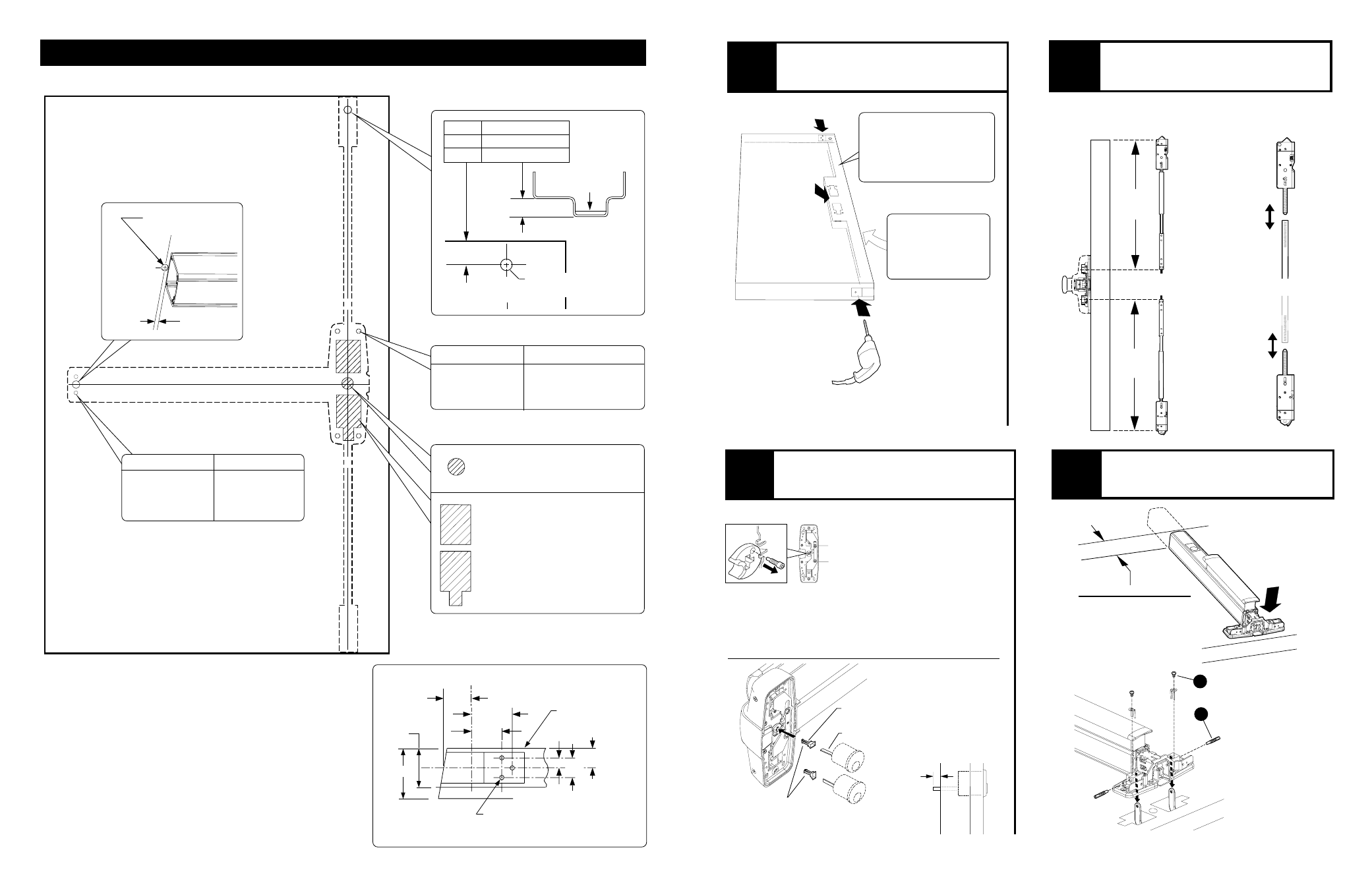
DOOR PREPARATION CHART
*End cap brkt. - 2 holes
C
L
Latch case
2-1/4"
1- 3/4"
1-7/32"
1- 5/8"
7/8"
7/8"
7/16"
C
L
Latch
case
1/8" Drill pilot
hole 1" deep
3 places
Inside face
of door
1- 5/16"
Prepare all holes and cutouts shown if they are not already present on door
X
X
CL
CL
Door Cut-outs
For all 98/9947 and
98/9947-F devices:
Trace cut-outs from
plastic template
(cut device side only)
Outside cylinder applications:
Mark with template and cut-out:
Surface mount
Sex bolts
1/8 Drill
pilot 1 deep
13/32
Drill thru
*Prepare holes after lock side of device
is mounted and hinge side is leveled
Latch Cases
(Drill top and bottom of door)
8
Check device length and attach
device center case to two offset
links as shown.
Center case
(align with
mounting holes)
2 Minimum clearance
(with end cap removed)
If device is too long for
door, see Cut Device
on back cover
B
A
5
Cut tailpiece
if needed
1/2
Door surface
7
Tailpiece
Tailpiece guide
Rotate tailpiece
guide to match
tailpiece
If using an outside cylinder, check NL
drive screw and install tailpiece guide.
When installing trim that has a
functional lever, knob, or thumb
piece AND an outside cylinder to
lock and unlock the trim, remove NL
drive screw from back of device.
DO NOT remove NL drive screw for
the following trims:
NL, EO, DT, TP-2, L-2, and K-2.
With BE trim, device may need
rehanded. Look for instructions on
back of trim.
Note: When the NL
drive screw is left in
back of device, the
outside cylinder
will function only
as a Night Latch.
NL drive screw
3
Prepare door per preparation
chart on page 8.
If door does not have
cut-out for rods inside
lock stile, door must be
routed (see Door Routing
Instructions on page 7)
5
4
Assemble rods and latches and
adjust length for proper door height.
Follow red and blue instruction cards on
rods to set initial rod length
Fine tune the
overall length
by threading
latch in or out
of rod
Top
length
Bottom
length
See trim instructions
for pull side door
preparation. Line X-X
in trim instructions is
same as device C.
L
8
5
Center case - 4 holes
Surface mount
Sex bolts or 990 trims
1/8 Drill
pilot 1 deep
13/32
Drill thru
Chexit wiring access hole
Drill 5/8 diameter
wire access hole
5/16
Device
CL
Ratchet Release Hole
CL
Latch
11/16 1/2 Stop height
13/16 5/8 Stop height
15/16 3/4 Stop height
Drill 1/2 dia. hole
(inside face of door)
Reinforcing
required