Door routing instructions – Factory Direct Hardware Von Duprin 9947WDCEOF User Manual
Page 5
10
Hang door on frame and install top
strike and ratchet release.
338 top strike
See Frame Preparation on
page 9 for cutout and holes
Ratchet release
Strike
Shim
(if needed)
Spacer
(use when frame
has no door stop)
I
J
See Frame Preparation
on page 9 for holes
9
Secure device to door.
Device equal
height to bottom
of door on each end
D
E
Mark and prepare
2 mounting holes
and secure screws
(see page3)
Mounting
bracket flush
Trim
(optional)
C
See Screw Chart
on page 2 for screw
types and sizes
7
6
3-1/4
minimum
2 minimum
1/4
4
1/2 maximum
thickness blocking
shown this view only.
Not provided by Von
Duprin.
1/8
3-1/2
4
1/4
3-1/4
minimum
2 minimum
C
device
L
C
of routing
L
2-1/4 door
1-3/4 door
1
2-1/2
4
5
8
2-1/2
backset
1-1/4
39-13/16
to finished floor
1-5/16
7/8 to routing
11/16 reference top & bottom
L
C
1-7/16 minimum top & bottom
Note: Required door undercut is 1/4 from
finished floor (panic and fire) or 1/8
from threshold (panic only)
C
latch and vertical rod
L
C
device
L
Device preparation
shown this view
for reference only.
use plastic device
template to mark
device cut-outs
(device side only).
C
latch and vertical rod
L
1/2 diameter hole
locate and drill
(inside face only)
LHR shown
(RHR opposite)
inside face of
lock stile
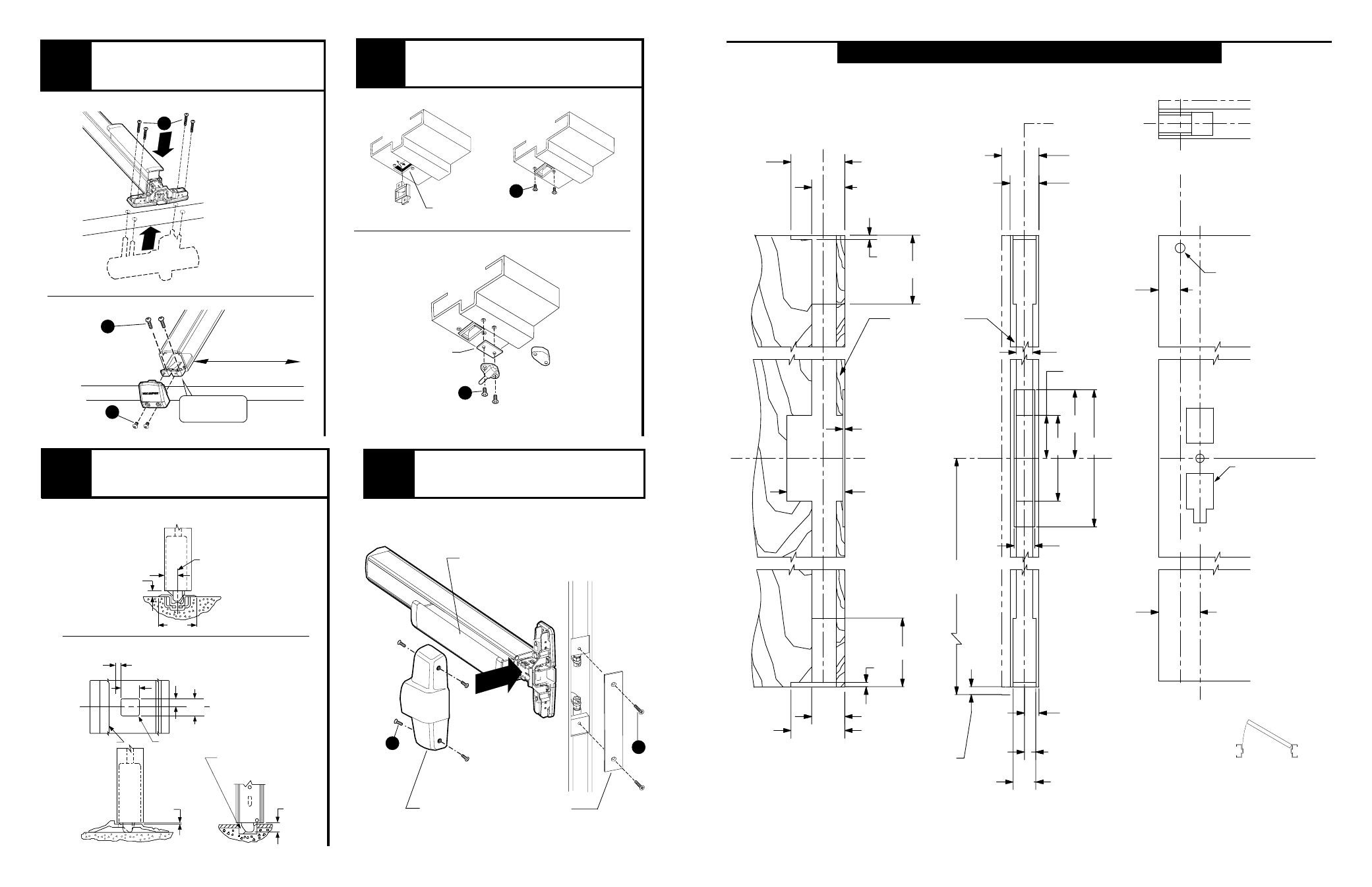
DOOR ROUTING INSTRUCTIONS
3/32"
R MAX.
STOP
9/16"
1 1/8"
3/8"
C
L
1/8"
LATCH CASE
5/8"
REMOVE MATERIAL
AS NECESSARY TO
ACCOMMODATE 5/8"
LATCH BOLT THROW
STRIKE
C
1/4"
1"
2 3/4"
L
11
12
Install bottom strike or
prepare threshold.
Adjust rods and install center
case cover and door cover plate.
385-A Bottom strike
Threshold application
Flat threshold
application
See Adjust Rods on page 10
for adjustment procedure
Center case
cover
K
Remove protective film
from pushbar
Door cover
plate
H