3B Scientific Electric Field Meter (115 V, 50__60 Hz) User Manual
Page 6
2
2. Description
The electric field meter is used for the measurement
of electrostatic field intensities or voltages.
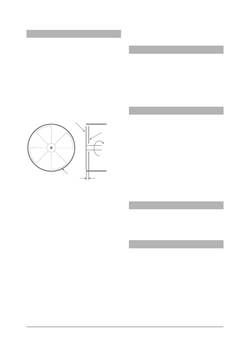
1. The principle for measuring electric field strength is
as follows: A shielding plate with four vanes
distributed in the shape of a star (induction plate) is
rotated in front of a detector plate (probe) of similar
shape. This arrangement means that the electric flux
surrounding the detector plate is continually
interrupted, so that an induced charge is generated
intermittently on the detector plate. This periodically
occurring charge is conducted away through a high-
value resistor. The voltage pulses thus generated are
amplified and rectified. The resulting output voltage is
proportional to the induced voltage, and therefore to
the strength of the electric field acting on the detector
plate.
1 mm
A
B
C
Fig. 1 A Shielding plate, B Induction plate, C Screening
cylinder
An ordinary DC voltmeter (with measurement ranges 1
V and 3 V) can be used to display the results. The 1V
range corresponds to electric field strength ranges of
100 V/cm, 300 V/cm or 1000 V/cm, selected by turning
the rotary selector switch knob to one of the three “E”
positions.
2. The principle of the electric field meter when used
as an induction electrometer is as follows: A capacitor
plate (the voltage measurement plate) is positioned at
a precisely defined distance from the detector plate
(probe). The combination of the two forms a capacitor,
and the electric field strength within it is a function of
the capacitor voltage and the distance between the
plates.
With the range switch set to one of the “U” positions, a
voltage applied to the voltage measurement plate is
indicated on the voltmeter. When the voltage
measurement plate is positioned at the shorter of the
two distances, a meter reading of 1 volt corresponds
to a measured voltage of 10 V, 30 V or 100 V,
depending on the position of the switch in the “U”
range. When the voltage measurement plate is
positioned at the greater distance, the measurement
ranges are increased by a factor 10.
The instrument is fully protected against excess
voltage, even if a spark discharge occurs.
3. Equipment Supplied
1 Electric field meter, basic instrument
1 Voltage measurement plate for measurement range
1
×
1 Voltage measurement plate for measurement range
10
×
1 Capacitor plate for voltage measurements, 250 cm
2
1 Capacitor plate on stem, 250 cm
2
20 Plexiglas spacer discs, 1 mm
4. Technical Data
Operating mains voltage: see back of instrument
Output voltage:
max. 10 V
Measurement ranges (corresponding to 1V output):
100 V/cm, 300 V/cm,
1000
V/cm
10 V, 30 V, 100 V (with voltage
measurement
plate
1x)
100 V, 300 V, 1000 V (with
voltage measurement plate 10x)
Input resistance:
10 M
Ω
Dimensions: 140
Ч110Ч70 mm
3
approx.
Weight:
1 kg approx.
The U8533015-230 electric field meter is designed for
a mains voltage of 230V (±10%), and the U8533015-
115 model for 115V (±10%).
5. Recommended Accessories
Analog multimeter AM50
U17450
Accessories for the electric field meter
U8533050
Contact rod
U8497730
Resistor 300 k
Ω
U51013
6. Operation
6.1 General instructions
•
Whenever possible, conduct the experiments
using voltages that are not dangerous to the
touch.
•
When using mains-connected instruments that
generate a voltage that would be dangerous to
touch, use a resistor (U51013) to limit the current.
•
For all measurements, connect the contact rod to
the earth socket on the screening cylinder and
hold it in your hand, so that you are also at the
same potential.
•
Before each set of measurements, the zero-point
of the electric field meter should be calibrated for
all the measurement ranges.