Newport Brass Toiletry Shelves_ Trays User Manual
Glass shelf installation instructions, Model no
2001 CARNEGIE AVE
SANTA ANA, CA 92705
©2010 Brasstech, Inc. Newport Brass is a registered trademark of Brasstech, Inc.
www.newportbrass.com
Glass Shelf
Installation Instructions
Model No.
10-16, 10-17, 12-16, 12-17, 13-16, 13-17, 15-16,
15-17, 16-16, 16-17, 17-16, 17-17, 19-16, 19-17,
22-16, 22-17, 23-16, 23-17, 24-16, 24-17
Recommended Installation by a Professional Contractor
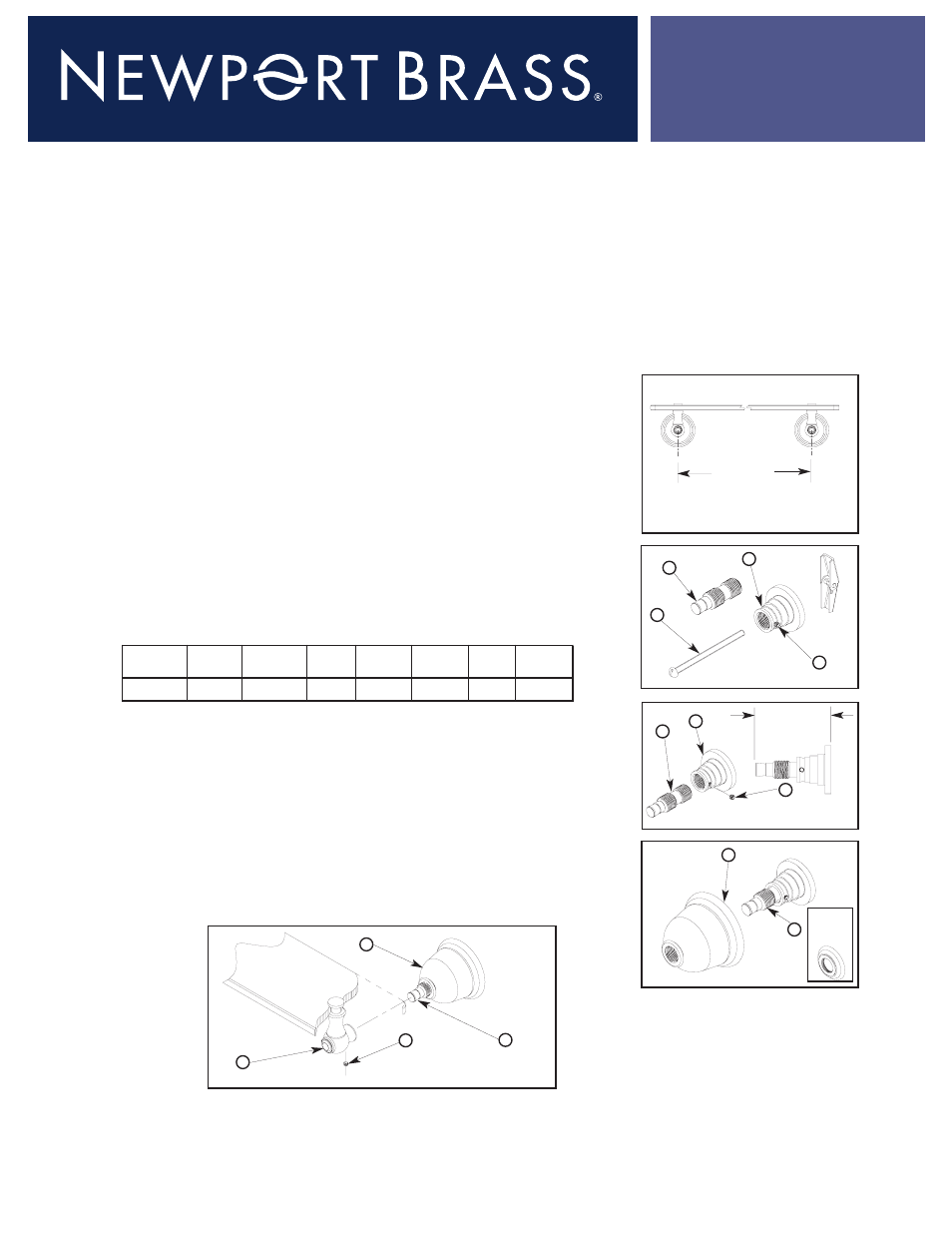
1. Using the table below, measure the appropriate distance between post centers. (See Fig. 1)
Note: Hole locations should be level.
· 18” Glass Shelf - 14”
· 24” Glass Shelf - 20”
2. Drill hole(s) in wall at points marked using the appropriate drill size:
· Wood Screw (#10 x 1-3/4”) - use: 1/8" Drill
· Toggle Screw (10-24 x 3”) - use: 9/16" Drill
3. Loosen the SETSCREWS (4) in FLANGES (1) and remove POSTS (2). Fasten FLANGES (1) to wall using
either WOOD/TOGGLE SCREWS (3). (See Fig. 2)
4.Thread POSTS (2) into FLANGES (1). Position POSTS (2), per Table below, at the proper height from
mounting surface. Secure into place by tightening SETSCREWS (4). (See Fig. 3)
5. Place ESCUTCHEON (5) onto POST (2).
Where applicable to your model, a DECORATIVE RING (5A) will be located under the
ESCUTCHEON (5). (See Fig. 4)
6.Attach GLASS SHELF END POSTS (6) to FLANGE POSTS (2) against ESCUTCHEON (5). Secure into place
with SETSCREWS (4). (See Fig. 5)
Distance
between posts
Post Height
See Table
Fig. 1
Fig. 2
Fig. 3
Fig. 4
Fig. 5
(949)417-5207
AMS-10-16 Santa Ana CA 92705 1/14/04
www.brasstech.com
2
4
3
1
2
4
1
5
2
MODEL
10-, 15-
23-
12-
16-
13-, 19-
24-
17-, 22-
POST HT.
2 5/16"
2 9/16"
2 3/8"
1 15/16"
2 1/8"
2 1/16"
2 3/16"
Where
Applicable
(5A)
4
2
6
5