Newport Brass 10-57 Annabella User Manual
Page 2
AMS-10-57
Recommended Installation by a Professional Contractor
1. Install wall support, by means of angle iron or wood blocking, at the required counter
height, (32"). (Note: material for this step is not included.)
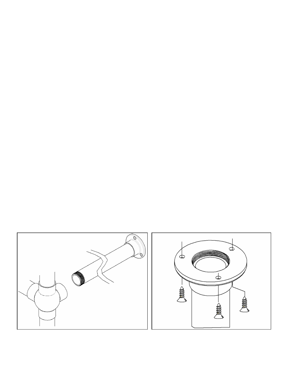
2. Thread end of return assemblies to the console stand. (See Figure A)
3. Install counter top, supporting front edge with console stand frame. Locate frame within
required parameters, shown below. Ensure that the frame and counter top are parallel
to floor and perpendicular to wall.
4. Mark hole pattern location of console top and wall flanges. Mark foot peg locations on
the floor.
5. Remove console stand and counter top. Pre-drill the foot peg holes in floor (Ø 5/16" x
.38 deep). Pre-drill hole pattern for wall flanges.
6. Attach console stand to counter utilizing (6) #8 x ½" wood screws and a suitable con
struction grade adhesive. (See Figure B) Thread foot pegs into place. (See Figure C)
7. Re-install the assembled counter and console stand using foot peg hole locations in floor
and wall support. Secure counter to wall with wall flanges on returns, (See Fig. D), and
anchor counter to wall support.
Note: Instructions are for general installation, variances in flooring, wall and
counter surfaces must be taken into consideration.
Figure A
2 places
Figure B
2 places