Newport Brass 1-563 User Manual
In-wall lavatory kit, Installation instructions, Model no. 1-563
In-Wall Lavatory Kit
Installation Instructions
Model
No. 1-563
We recommend Installation of this product by a Professional Plumbing Contractor
Note: Use Teflon tape or equivalent to seal all threaded port joints.
Warning: To prevent severe damage to valve body, any solder/braze process must be performed a min. of 4” from
ports.
Important: REMOVE CARTRIDGE FROM VALVE BODY (1) PRIOR TO APPLYING ANY HEAT/FLAME.
Utilizing a 3/4” copper supply piping, thread or sweat pipe fittings into inlets of valve BODY (1), (blue STEM (4) is cold,
red STEM (5) is hot). If sweating supplies directly to valve inlets, remove cartridges during this process.
Note: If cartridges are removed during installation, re-torque to factory specification of 14-16 ft-lbs.
Attach supply source to inlet of VALVE (1). Water flow direction is indicated by "ARROW" on side of body.
Attach end device to outlet of VALVE (1).
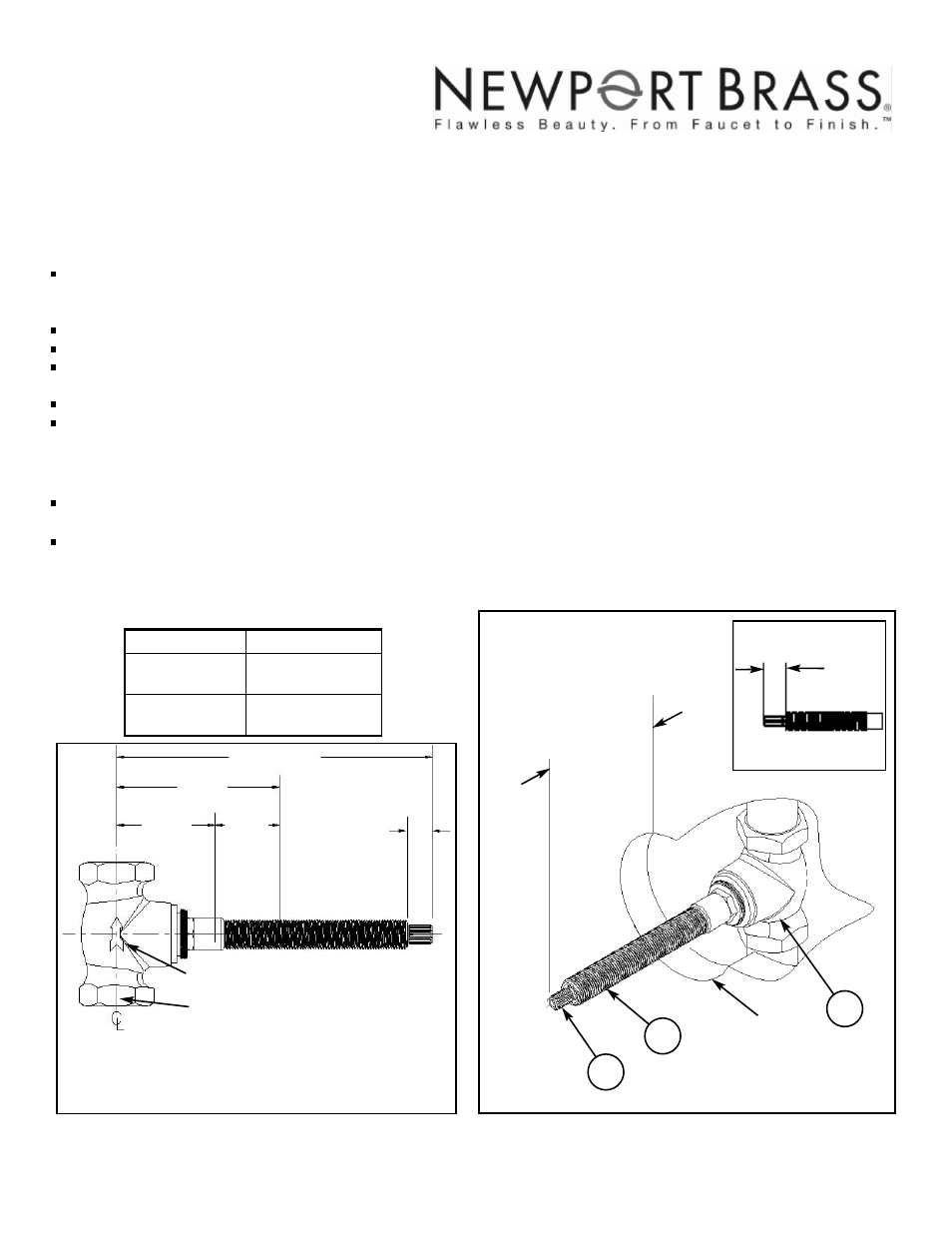
Position VALVE (1) in wall as shown below. These dimensions are for typical installations. If thick finished wall materi-
als are to be used in construction, it is recommended that VALVE (1) is positioned toward outer face of stud.
Support VALVE (1) and/or piping to stud framing using strap tape or equivalent.
Turn on water supply, pressurize system and check for leaks.
Finished wall dimensions are shown in Figure 2.
Finished wall surface must be completed before proceeding.
Measuring and cutting stem length:
Remove ALL-THREAD (3) and indicate on STEM (2) a measured distance, (see Table 1), from finished wall surface. Using
a hacksaw, cut off excess length of STEM (2).
Trim additional 1/2” of ALL- THREAD (3) length from end of STEM (2). See Figure 1A.
For handle trim attachment, the following table shows required stem length from finished wall:
Stem Length
Trim Model #
1-5/16”
3-424
3-423
1-3/16”
3-425
1/2”
See Table 1
Finished wall
3
2
Figure 1A
Figure 1
6”
max.
f
inished wall
1/2”
*
3”
1-1/4”
Face of stud
Outlet
Inlet
2 x 3/4-14 NPT (1-563)
*
1-3/4”
Direction of water flow
*
If finished wall material is thicker than stated “Mud/ Tile max”, then the
“Face of stud” dimension must be less than shown.
Mud/
Tile
max.
Ø1”
1
Figure 2
Table 1
NWP 1-563
EN-2446
REV -
01/25/2013
2001 CARNEGIE AVE, SANTA ANA CA 92705
(949) 417-5207
WWW.NEWPORTBRASS.COM