Warning, Gf e a, Ag f – Peerless-AV PRS-1S - Installation User Manual
Page 6: Installation to concrete ceilings
ISSUED: 08-15-07 SHEET #: 055-9188-7 01-18-11
Visit the Peerless Web Site at www.peerlessmounts.com
6 of 13
For customer care call 1-800-865-2112 or 708-865-8870.
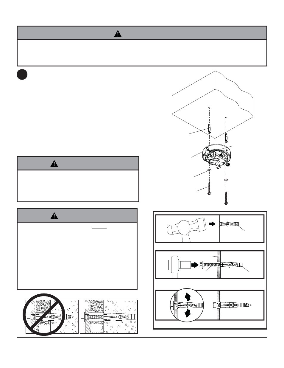
Place projector mount assembly (A) on ceiling
as a template and mark the center of the two
mounting holes. Drill two 5/16" (8 mm) dia. holes to
a minimum depth of 2.5" (64 mm). Attach projector
mount assembly (A) using two concrete anchors
(G), two fl at washers (E), and two #14 x 2.5" wood
screws (F) as shown.
Note: Mounting slots on projector mount assembly
allow for 30° (±15°) of rotation before fully securing
wood screw.
Tighten wood screws (F) using 3/8" (10 mm) socket
wrench or phillips screwdriver until projector mount
assembly (A) is fi rmly attached.
Skip to step 5.
Installation to Concrete Ceilings
FRONT OF
MOUNT
• Tighten wood screws fi rmly, but do not overtighten.
Overtightening can damage the screws, greatly re-
ducing their holding power.
• Never tighten in excess of 80 in • lb (9 N.M.).
WARNING
3
• Always attach concrete anchors directly to load-
bearing concrete.
• Never attach concrete anchors to concrete covered
with plaster, drywall, or other fi nishing material. If
mounting to concrete surfaces covered with a fi nish-
ing surface is unavoidable (not evaluated by UL), the
fi nishing surface must be counterbored as shown be-
low. Be sure concrete anchors do not pull away from
concrete when tightening screws. If plaster/drywall is
thicker than 5/8", custom fasteners must be supplied
by installer (not evaluated by UL).
WARNING
• Concrete must be 2000 psi density minimum. Lighter density concrete may not hold concrete anchor.
• Make sure that the supporting surface will safely support the combined load of the equipment and all attached hard-
ware and components.
WARNING
G
F
E
A
CUT
A
W
A
Y
VIEW
INCORRECT
CORRECT
plaster/
dry wall
plaster/
dry wall
concrete
concrete
1
3
2
G
Drill holes and insert anchors (G).
Place plate (A) over anchors (G) and secure with screws (F).
Tighten all fasteners.
A
G
F
concrete
surface
A
A