Warning, Fe j, Je j – Peerless-AV PC932C-W - Installation User Manual
Page 10: Fl d
10 of 35
ISSUED: 11-29-07 SHEET #: 202-9263-2 08-17-11
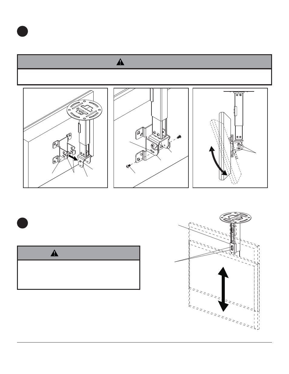
Guide hook slots of tilt bracket (F) onto M5 x 10 mm screws (J) in swivel/pivot bracket (E) as shown in fi gure 6.1.
Thread two M5 x 10 mm screws (J) through tilt slot of tilt bracket (F) into swivel/pivot bracket (E) as shown in
fi gure 6.2. Do not fully tighten screws to allow for tilt adjustments. Tilt slot allows for incremental tilts of 5°.
Adjust tilt of display and fully tighten all four M5 x 10 mm screws (J) as shown in fi gure 6.3.
fi g. 6.1
fi g. 6.2
fi g. 6.3
F
E
J
HOOK
SLOTS
J
E
J
Attaching Display
Adjusting Mount Extension
While supporting the weight of the display, loosen
screws (L) on clamp plate (D) half a turn and
position display to the desired height.
Retighten clamp plate screws securely.
CLAMP PLATE
SCREWS
TILT
SLOTS
F
L
D
6
7
• Clamp plate adjustment screws support weight of
display when fully tightened. Weight of the display
will need to be supported if clamp plate screws are
loosened.
WARNING
• Do not lift more weight than you can handle. Use additional man power or mechanical lifting equipment to safely
handle placement of the display.
WARNING