Top tray installation, Xw y – Peerless-AV PSM-UNV-W - Installation User Manual
Page 6
ISSUED: 08-09-06 SHEET #: 055-9469-3 06-15-10
Visit the Peerless Web Site at www.peerlessmounts.com
6 of 9
For customer care call 1-800-729-0307 or 708-865-8870.
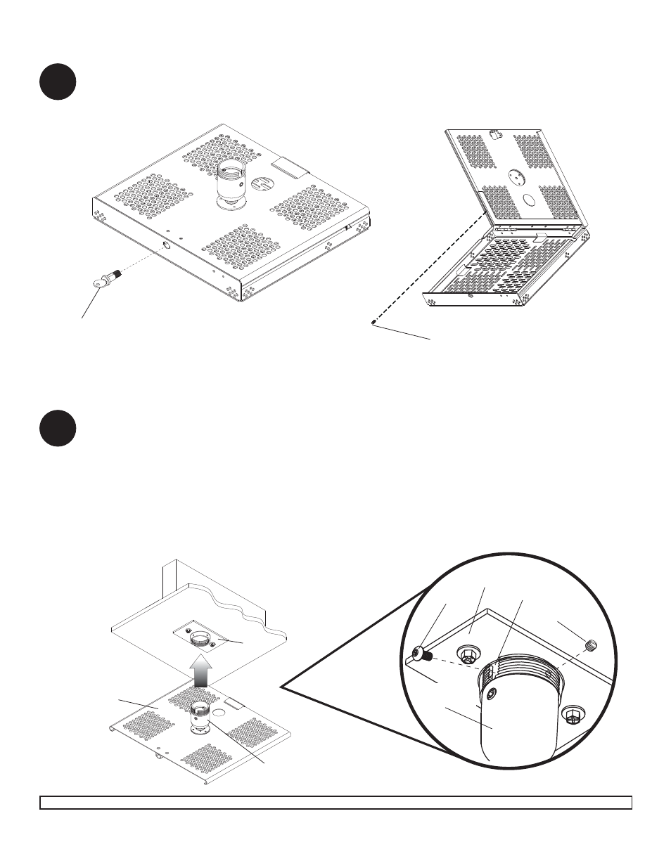
2
Remove the lock plug (S) by using key to unscrew it from the assembly as shown in detail 2.1. Open the mount
and remove thumb screw as shown in detail 2.2.
NOTE: The upper tray of the mount will now slide off of the lower tray.
DETAIL 2.1
DETAIL 2.2
S
THUMB SCREW
Thread tilting mechanism of top tray into ceiling plate (Y). Align the notch with one of the four holes of the ceil-
ing plate (Y) and secure tilting mechanism with a M5 x 10 mm socket pin screw (W) using 4mm security allen
wrench (R) as shown in detail 3.
NOTE: Slotted set screw (X) is used to jam against the threads of the tilting mechanism to prevent any excess
movement of the upper tray. Do not overtighten screw; overtightening screw will damage threads making it dif-
fi cult to separate the products.
IMPORTANT! Be sure not to touch the projector while tightening the set screw on the tilting mechanism. This
may cause the image to be unaligned when you let go.
Y
WOOD JOIST
CEILING
UPPER TRAY
TILTING
MECHANISM
3
Top Tray Installation
DETAIL 3
X
W
Y
TILTING
MECHANISM
NOTCH
For Extension Column Installation, skip to step 3A