485ldrc9, First things first, Troubleshooting fast, easy answers – B&B Electronics 485LDRC9 - Quick Start Guide User Manual
Page 2: Recommended accessories and power supplies, Before you begin, be sure you have the following
Troubleshooting
Fast, Easy Answers
Timing Issues?
(Usually applies when using 2-wire 485)
The 485LDRC9 uses RC time constant. This means that when you
are setting the DIP switches for the “baud rate” you are setting a
turnaround time, not a “baud rate”.
Sometimes the turnaround time on a RS-485 2-wire device does not
match the turnaround time that is set on the 485LDRC9, even though
they are both set for the same baud rate. Refer to the chart in
Step 3 to match the turnaround time of your RS-485 2-wire device.
If you do not know the turnaround time of your device you can do the
following:
• Keep your device at its current baud rate, but change
the “baud rate” on the 485LDRC9. Set it for one
or two steps above or below the baud rate of your
device until you get communication.
• Alternatively, you can use the 485DRCi-PH instead of
the 485LDRC9. The 485DRCi-PH uses bitwise control
so you do not have to worry about matching the
timing of your device.
Check Type of Cable Used
A 24 gauge twisted pair, shielded cable is preferred. Category
5 cable is available as shielded twisted pair (STP), as well
as unshielded twisted pair (UTP) and generally exceeds the
recommendations for RS-422, making it an excellent choice
for RS-422 and RS-485 systems.
Are You Hooking a Signal Ground
(common, reference) on the RS-422/485 side?
The specifications for most RS-422 and RS-485 devices indicate that
the device can withstand a maximum VCM of -7 volts to +12 volts.
The function of the GND connection is to tie the signal grounds of all
nodes on a network to one common ground potential. This ensures
that the common mode voltage cannot exceed the specified value.
A signal ground is required on the 485LDRC9 because it is an
optically isolated device. If you do not have a signal ground
(common, reference) on your RS422/485 device, you can hook to the
DC power ground of your RS422/485 device.
Caution: Make sure that this is connected correctly.
Note: Do not use the shield drain wire as the signal ground between RS-422/485 devices.
RS-422/485 systems may communicate successfully without the signal ground when nodes
are located close together and circuit grounds for all nodes are at the same potential--e.g., a
controlled lab environment. However, this practice is not recommended. If a signal ground is
not used when nodes are separated by distance, and there is the possibility of lightning and/
or other electrical noise, the common mode voltage can rise to levels that could compromise
communications, or even damage the transceivers in the system nodes.
Fast and easy on the web:
www.bb-elec.com
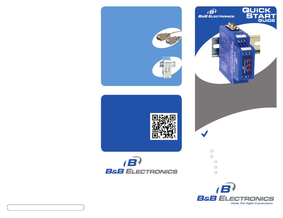
Optically Isolated
RS-232 to RS-422/485 Converter
485LDRC9
© 2012 B&B Electronics Manufacturing Company
1-888-948-2248 | Europe: +353 91 792444
www.bb-elec.com
Recommended Accessories
and Power Supplies
http://www.bb-elec.com/485LDRC9/
ACC
http://www.bb-elec.com/485LDRC9/
ACC
• First, check step 6.
• Then use your smart
phone to access complete
documentation on our
web site. Simply scan
the code to the right.
Industrial Power Supplies
Ready To Use Cables For
Serial And USB
MDR-40-24
9PAMF6
485LDRC9 Serial Converter
Additional items required but not included:
Power Supply
RS-232 Cable
RS-422/485 Cable
707 Dayton Road | PO Box 1040 | Ottawa, IL 61350
Phone: 815-433-5100 | Fax: 815-433-5109
www.bb-elec.com | E-mail: [email protected]
Document number – p/n 8413 r003 485LDRC9 - 1112
http://www.bb-elec.com/485LDRC9
First Things First...
Before you begin, be sure you have
the following: