B&B Electronics 485LDRC9 - Quick Start Guide User Manual
Product overview, Termination switch, Set the dipswitch settings for baud rate
Set The 422/485 Side of Converter
Connect Your RS232 Device
(Terminal Block OR DB9 Port)
Computer
Termination Switch:
Set to OFF (Recommended)
Switch 5
If you want to enable termination,
refer to:
http://www.bb-elec.com/
485LDRC9
Set the Dipswitch Settings for Baud Rate
For baud rates not listed above refer to:
http://www.bb-elec.com/485LDRC9
Additional tech notes on RS232 DTE DCE connections
are located at:
http://www.bb-elec.com/tech/DTE-DCE
Loopback Test
(Optional)
To verify serial port and 485LDRC9 functionality
• Configure for RS-485 four wire,
9600 baud.
• Jumper terminals H to L and G to K.
• Connect a PC to the RS-232 port
(see Step 1).
• Using HyperTerminal or similar program,
connect to the appropriate COM port
(remember to set the baud rate at 9600).
Turn off HyperTerminal local echo.
• Start typing. If you can see the data
you are typing, you have a good loop-
back. If you cannot, contact tech support.
• LED Indicators: Power is ON when power
is applied. TD flashes when RS-422/485
data is sent. RD flashes when RS-422/485
data is received.
Set DIP
Switches to:
Your Device
485LDRC9
• Use a straight through DB9 to DB9 if you are
connecting to a computer (DTE).
• Use a cross over (null modem) DB9 to DB9
if you are not connecting to a computer. (DCE)
Additional tech notes on 422/485 are located at:
http://www.bb-elec.com/485LDRC9
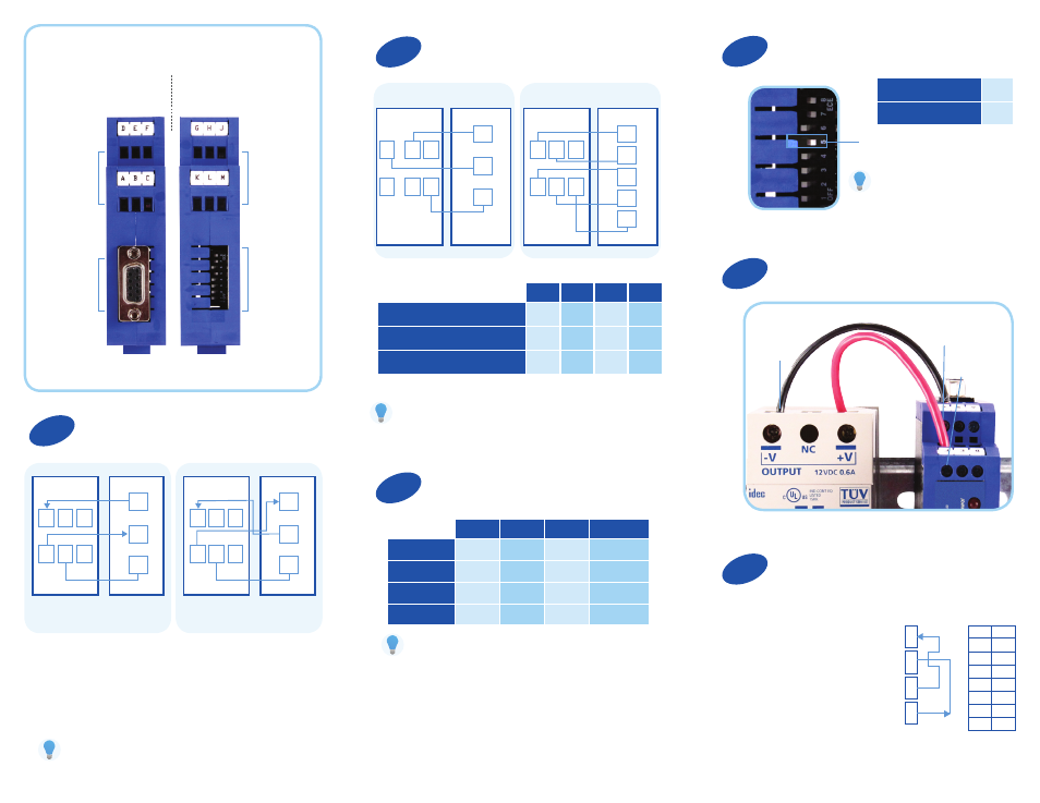
Product Overview
Terminal Block
Connectors
A – F
Terminal Block
Connectors
G – M
DB9 F PINS
DIP Switches
1 – 8
Top View
(232 and Power Side)
Bottom View
(422/485 Side)
Connect Your Power Supply
External Power
Supply
Terminal C:
(Ground/V (–)
Terminal F:
V (+)
Field Device
Your Device
485LDRC9
Please Note:
Terminal block and DIP switch settings located on product.
2 Wire 485
4 Wire 485/422
Your Device
Your Device
485LDRC9
485LDRC9
DTE
DCE
Converter uses 0.5 W
RS-485 4-Wire
G
K
DATA
B (+)
DATA
A (-)
GND
H
L
J
M
G
TDB (+)
TDA (-)
RDB (+)
RDA (-)
GND
K
H
L
J
M
D
TD
RD
A
E
B
F
C
GND
D
TD
RD
GND
A
E
B
F
C
L
K
H
G
1
2
3
4
5
6
7
8
ON
ON
OFF
OFF
OFF
OFF
OFF
OFF
SW-1
SW-2
SW-3
SW-4
RS-485 2-Wire Half Duplex
ON
ON
ON
ON
RS-485 4-Wire Full Duplex
ON
OFF
OFF
OFF
RS-422 Full Duplex
OFF
OFF
OFF
OFF
SW-6
SW-7
SW-8
Timeout (MS)
2400
OFF
OFF
ON
4.16
4800
OFF
ON
OFF
2.08
9600
ON
OFF
OFF
1.04
19.2K
ON
ON
ON
0.580
Use the 120Ω
Built-in Termination
ON
Use External or
No Termination
OFF
2
1
5
4
3
6