B&B Electronics 485OPDR-HS - Quick Start Guide User Manual
Connections, Dip switches wiring example
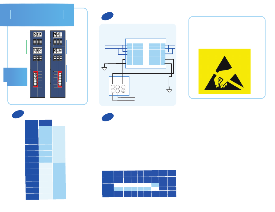
Connections
3
1
Terminal Block
Connectors
A – F
Terminal Block
Connectors
G – M
DIP Switches
1 – 8
DIP Switches
Wiring Example
Terminal
Block
Signal
A
OUT (+)
A-F Side
B
OUT (-)
C
Signal
Ground
D
Power
Ground
E
IN (+)
F
IN (-)
G
IN (+)
G-M Side
H
IN (-)
J
+10 to 30
VDC
K
OUT (+)
L
OUT (-)
M
Signal
Ground
2
Set DIP switches for RS-422, 2-Wire RS-485
or 4-Wire RS-485. The sample settings shown
below are for 2-Wire RS-485 half duplex
operation.
Switches 1, 2, 3, 4, 5 = ON
Switch 6 = OFF
Switches 7, 8 = Not Used
RS-485 Echo
Off
2W 2W
Bias
IN
Term
IN
Not
Used
Not
Used
Switch
1
2
3
4
5
6
7
8
Position
ON
ON
ON ON ON
ON
***
***
OFF
OFF
OFF OFF OFF
OFF
***
***
RS-422 Echo
On
4W 4W
Bias
OUT
Term
OUT
Not
Used
Not
Used
H
In -
G
In +
L
Out -
K
Out +
J
10-30
VDC
M
IGND1
Out -
B
Out +
A
In -
F
In +
E
GND
D
IGND2
C
2-Wire RS-485 System
TD/RD(A)-
TD/RD(B)+
GND/REF
Signal
Ground
POWER
SUPPLY
AC Power lines
or AC outlet
using plug
Cable is 2 twisted pairs
+ shield (not shown)
485OPDR-HS
.
.
.
.
-V NC +V
L N
Attention: Please follow proper ESD
protection procedures when configuring
this device.
- USOPTL4DR-LS - Datasheet (2 pages)
- ZXT9-IOA-KIT - Manual (75 pages)
- ADAM-6066 - Manual (272 pages)
- 855-11619--57 - Datasheet (2 pages)
- 851-10904 - Datasheet (2 pages)
- SS-BLT-100PR - Quick Start Guide (1 page)
- ISOCON-6 - Datasheet (2 pages)
- I-7060 - Manual (64 pages)
- AMU864 - Datasheet (2 pages)
- 714FX6-SC_ST - Manual (154 pages)
- 422LP25R - Datasheet (2 pages)
- ZP9D-115RM-LR - Manual (54 pages)
- EKI-6311GN-EU - Manual (56 pages)
- ZZ24D-NA(NB,NC,ND)-SR - Quick Start Guide (4 pages)
- ESCLP-100 - Manual (23 pages)
- 806-39753 - Datasheet (1 page)
- 485SD9RJ - Datasheet (1 page)
- 712FX4-SC_ST - Manual (154 pages)
- 850-18610 - Manual (18 pages)
- ESW208 Series - Datasheet (2 pages)
- VESR321_ML_SL - Quick Start Guide (3 pages)
- OP10 - Datasheet (1 page)
- RT3G-300_310_320_330_340-W - Configuration Manual (79 pages)
- EIRHP305-T - Datasheet (2 pages)
- EIRSP1 - Datasheet (1 page)
- 422TTL33 - Datasheet (2 pages)
- 485DRCI - Quick Start Guide (2 pages)
- I-7021_P - Datasheet (2 pages)
- NTSA-CAT5E - Datasheet (2 pages)
- 485COSR - Datasheet (2 pages)
- 855-10619--57 - Datasheet (2 pages)
- UH401SL_2KV - Datasheet (2 pages)
- 105FXE-SC(ST)-15-POE - Manual (19 pages)
- 102MC-FL_SC_ST - Manual (23 pages)
- CBL00302 - Datasheet (1 page)
- 850-18100--27 - Datasheet (2 pages)
- 850-10953-DC - Datasheet (2 pages)
- ESR904 - Datasheet (2 pages)
- 308TX-N - Datasheet (3 pages)
- 422LP25N - Datasheet (2 pages)
- 708FX2-SC_ST - Datasheet (3 pages)
- MESR321_SL_ML - Datasheet (2 pages)
- SL2736-698 - Quick Start Guide (8 pages)
- I-7188E Series - Datasheet (1 page)
- ANT-PAD58-19 - Datasheet (1 page)