B&B Electronics 232OPDRI - Quick Start Guide User Manual
Product overview, Loopback test connect your rs-232 devices, Check leds
LED
Indicators
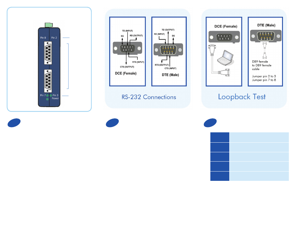
Loopback Test
Connect Your RS-232 Devices
Front View
LED
Indicators
Serial
Ports
• Use a DB9 Female to DB9 Male cable to connect
a PC to the DCE port. (Recommended)
• Connect a DB9 Female to DB9 Female cable
to the DTE port. On the DTE Port, jumper pin
2 to 3 and pin 7 to 8 on the female end
of the cable. This loops TD to RD and CTS to RTS.
• Using HyperTerminal or similar program, connect
to the appropriate COM port. (Remember to set
the baud rate to 9600.)
• Turn off HyperTerminal local echo.
• Type some characters in HyperTerminal. The
same characters should appear on your screen.
The LED indictors will light up to show you that
data is being transmitted.
Check LEDs
Product Overview
10 to 48 VDC
1.5 W Max
A DTE device is “Data Terminal Equipment.” This
includes computers, PLCs, and most devices that are
not used to extend communications.
(Think “COMPUTER” for DTE.)
A DCE device is “Data Communications
Equipment.” This includes modems and other
devices that extend communications, like RS-422,
RS-485, fiber optic converters or radio modems.
(Think “MODEM” for DCE.)
When connecting a DTE device to a DCE device,
use a straight through connection. When connecting
a DTE device to a DTE device, or a DCE device to a
DCE device, use a crossover (null) connection.
Pin 2 LED
Red, Flashes when RD present on DTE port
Pin 3 LED
Red, Flashes when TD present on DCE port
Power LED
Red, ON when power applied
Pin 7 LED
Red, Flashes when RTS raised on DCE port
Pin 8 LED
Red, Flashes when CTS raised on DTE port
1
2
3