B&B Electronics ZP9D-115RM-LR - Quick Start Guide User Manual
Page 2
Documentation Number –p/n 8577R1 ZP9D-115RM-LR-0812qsg
Click the Update Button to store the settings.
Click the Advanced Modem Settings TAB. Check the Power
Level (PL). Select the appropriate power level for your
application. For bench testing, PL should be set to 0 and
Radio Modems should be separated by at least 1 meter.
When using higher power levels, separate the modems by
at least 7 meters.
If you changed any settings, store them by clicking the
Update button.
S
S
e
e
t
t
u
u
p
p
y
y
o
o
u
u
r
r
s
s
e
e
c
c
o
o
n
n
d
d
R
R
a
a
d
d
i
i
o
o
M
M
o
o
d
d
e
e
m
m
Exit Configuration. Power off the Radio Modem (wait at least
30 seconds before re-applying power to this Radio Modem.
Configure your second Radio Modem using the same
procedure. Do not proceed to the RSSI Range Test step until
you have a second modem configured. Two properly
configured units are required to proceed to the next step.
Configure the second unit with the same settings.
C
C
o
o
n
n
f
f
i
i
g
g
u
u
r
r
e
e
t
t
o
o
M
M
a
a
t
t
c
c
h
h
Y
Y
o
o
u
u
r
r
S
S
e
e
r
r
i
i
a
a
l
l
D
D
e
e
v
v
i
i
c
c
e
e
s
s
Configure the Radio Modems to match the serial devices
you will be connecting to.
The DB9 is wired as a DCE device. If you are connecting to
another DCE device, a cross-over cable will be required.
For the RS-422/485 terminals, TD is output, RD is input.
Ensure you match the signal polarity.
o
2-Wire Mode: TDA(-) TDB(+), SW1 & 2
ON.
o
Wiring Examples are located in the
manual.
You are now ready to install your Radio Modems in the field.
R
R
S
S
S
S
I
I
R
R
a
a
n
n
g
g
e
e
T
T
e
e
s
s
t
t
Set one the remote modem to Loopback Mode. Loopback
connections can be made using the RS-422/485 interface
by setting switch 1 and 2 to ON and 3 and 4 to OFF
(internal loopback with echo on). You can also use the DB9
connections by bridging pins 2 and 3.
On the Radio Modem that is NOT set up for Loopback Mode,
run the RSSI Range Test. Observe the following
indications:
o
The DATA and RSSI will flash as data is
sent between the two units.
o
Test results will be displayed on the RSSI
Range Test Screen.
6
8
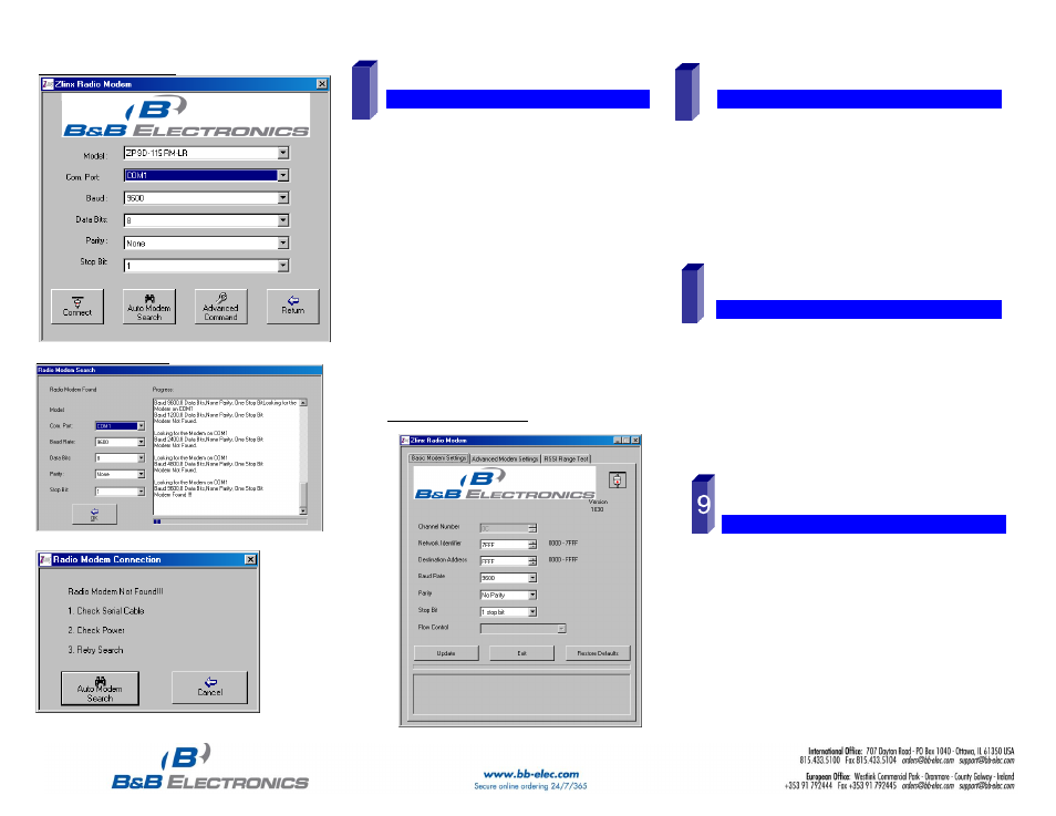
On-line Configuration Screen
Radio Modem Found Screen
Radio Modem Not Found Screen
S
S
e
e
t
t
u
u
p
p
t
t
h
h
e
e
R
R
a
a
d
d
i
i
o
o
M
M
o
o
d
d
e
e
m
m
Select a unique Network Identifier. This is especially
important if you have other units operating in the same
area.
Set the Destination Address to FFFF (broadcast).
If desired, you can change the baud rate and parity on the
Basic Modem Settings Screen. Remember to change your
COM port to match.
Basic Modem Settings Screen
7