B&B Electronics ZP9D-115RM-LR - Quick Start Guide User Manual
Quick start guide
Documentation Number –p/n 8577R1 ZP9D-115RM-LR-0812qsg
C
C
h
h
e
e
c
c
k
k
f
f
o
o
r
r
A
A
l
l
l
l
R
R
e
e
q
q
u
u
i
i
r
r
e
e
d
d
H
H
a
a
r
r
d
d
w
w
a
a
r
r
e
e
ZLINX™ ZP9D-115RM-LR
This Quick Start Guide
CD with ZLINX™ Manager Software and manual
Antenna
Terminal Block (Attached)
Additional items required but not included:
o
10 – 48 VDC / 18 – 30 VAC) 6.0 W Power Supply
o
Serial Cable
Special Precautions for UL and UL Class I DIV 2
WARNING – EXPLOSION HAZARD – SUBSTITUTION OF
COMPONENTS MAY INPAIR SUITABILITY FOR CLASS I,
DIVISION 2
WARNING – EXPLOSION HAZARD – WHEN IN HAZARDOUS
LOCATIONS, TURN OFF POWER BEFORE REPLACING
ANTENNA
WARNING – EXPLOSION HAZARD – DO NOT DISCONNECT
EQUIPMENT UNLESS POWER HAS BEEN SWITCHED OFF
OR THE AREA IS KNOWN TO BE NONHAZARDOUS
THIS EQUIPMENT IS SUITABLE FOR USE IN CLASS I,
DIVISION 2, GROUPS A, B, C, AND D OR UNCLASSIFIED
LOCATIONS
Maximum Ambient Air Temperature 85°C (185°F)
Wiring Terminals:
Copper Wire Only
One Conductor per Terminal
Wire Range 28 to 16 AWG
Tightening Torque 1.7 lb-in
Temperature Rating of Field Wiring – 105° C (221° F) sized
for 60° C (140°F) ampacity.
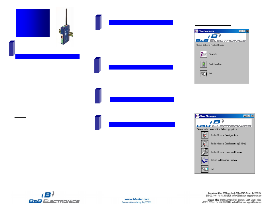
Radio Modem Options Screen
Quick Start
Guide
ZP9D-115RM-LR
Zlinx™ Radio
Modem
I
I
n
n
s
s
t
t
a
a
l
l
l
l
Z
Z
l
l
i
i
n
n
x
x
™
™
M
M
a
a
n
n
a
a
g
g
e
e
r
r
S
S
o
o
f
f
t
t
w
w
a
a
r
r
e
e
Insert the CD into your CD ROM Drive. The Zlinx™
Manager Install Wizard should start. Follow the on-
screen instructions to install the software.
If auto run is disabled, locate the Zlinx Manager file on
the CD and double click it. The Install Wizard should
start. Follow the on-screen instructions.
2
1
S
S
t
t
a
a
r
r
t
t
t
t
h
h
e
e
Z
Z
l
l
i
i
n
n
x
x
™
™
M
M
a
a
n
n
a
a
g
g
e
e
r
r
S
S
o
o
f
f
t
t
w
w
a
a
r
r
e
e
Start the Zlinx™ Manager Software.
Click the Radio Modem Button.
Click the Radio Modem Configuration Button.
o
Select your COM port and configure it for 9600 baud,
Data Bits: 8, Parity: None, Stop Bit: 1.
Click the Connect Button.
When the software locates the Radio Modem, the Basic
Modem Settings Screen will be displayed. This screen
will display the Model Number, Function Set Type,
Firmware Version, Network Identifier, Destination
Address, Baud Rate, and Parity.
If the settings where changed from the default, Auto
Modem Search can be used to locate the modem. The
Auto Search will use a sequence of COM Ports and
settings until a response is received. If there is still no
response, double check the power supply and serial
cable. Also, make sure that no other devices are
attached and that the unit is not set to RS-422/485 2-
wire.
5
C
C
o
o
n
n
n
n
e
e
c
c
t
t
P
P
o
o
w
w
e
e
r
r
S
S
u
u
p
p
p
p
l
l
y
y
A 10 to 48 VDC or 18 to 30 VAC external power supply
is required.
Connect the power supply to the power terminal block
located on the top of the radio modem.
3
4
C
C
o
o
n
n
n
n
e
e
c
c
t
t
S
S
e
e
r
r
i
i
a
a
l
l
C
C
a
a
b
b
l
l
e
e
&
&
A
A
n
n
t
t
e
e
n
n
n
n
a
a
Connect a straight through RS-232 cable between the
Radio Modem and your PC.
Connect the antenna to the Radio Modem.
Zlinx™ Manager Start Screen