B&B Electronics EIS-EXTEND-C - Quick Start Guide User Manual
Product overview, Set dip switch, Connect your power supply
Coax Line
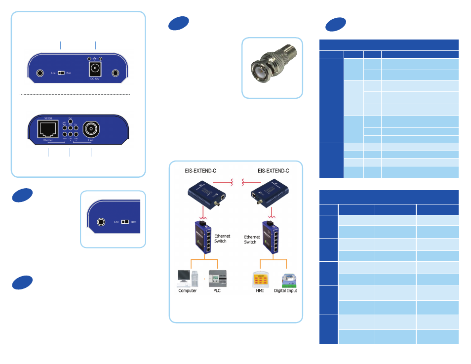
Product Overview
Rear View
Front View
DIP Switch
Set DIP Switch
Ethernet extenders work
in pairs. Set one as the
local (Loc) unit and the
other as the remote (Rem)
unit. It doesn’t matter which
one is which.
The DIP switch is on top of the device.
Connect Your Power Supply
Apply rubber feet to the bottom of the media
converter and select a suitable mounting location. The
unit can be wall-mounted using the slots on the bottom
of the case.
Connect the supplied AC to DC power adaptor to the
receptacle on the rear panel of the Ethernet extender.
Plug In Your Cable
Connect the Ethernet cable
to the RJ-45 port on the front
of the Ethernet extender.
Connect the coaxial cable
to the BNC port on the front
of the Ethernet extender. The
opposite end connects with
a paired Ethernet extender
located elsewhere. Coax
cable must be terminated
with male BNC to F
connectors. A BNC to F-Type
adaptor is required for the F
style connector (included).
Note: Extender must be connected to a receiving extender
or a network switch.
LED Status
12 VDC
Ethernet
LEDs
BNC to F-Type Adaptor
Top LEDs (BNC Line Connections)
LED
Status
Speed
Distance
1
Green
1-5 Mbps
up to 2600 M
Amber
6-10 Mbps
up to 2400 M
2
Green
11-16 Mbps
up to 2000 M
Amber
17-20 Mbps
up to 1800 M
3
Green
21-29 Mbps
up to 1600 M
Amber
30-43 Mbps
up to 1400 M
4
Green
44-54 Mbps
up to 1200 M
Amber
55-63 Mbps
up to 1000 M
5
Green
64-74 Mbps
up to 600 M
Amber
75-85 Mbps
up to 200 M
Front Panel LEDs (Ethernet and Line Connections)
Port
LEDs
Status
Description
Ethernet
(RJ-45)
Power1
Power2
Power3
Steady
Power on
Off
Power off
Link/ACT
Steady
Valid Ethernet connection established
Flashing
Transmitting or receiving Ethernet data
(ACT stands for Activity)
Off
No valid Ethernet connection nor transmitting/
receiving Ethernet data
FDX
Steady
Ethernet connection in full duplex mode
(FDX stands for FULL-DUPLEX)
Flashing
Collision occurred
Off
Ethernet connection in half-duplex mode
Line (BNC)
Remote
Steady
Operating in remote mode
Local
Steady
Operating in local mode
Error
Steady
Error occurred
Link
Steady
A valid connection established between local
and remote
1
2
3
4