2 connecting power, Figure 2.34 power connector, 3 connecting serial devices – B&B Electronics EKI-1222 - Manual User Manual
Page 35: Connecting power figure 2.34power connector, Chapter 2 g etting started
29 ADAM-4572 & EKI-122X Series User Manual
Chapter 2
G
etting
Started
2.4.2
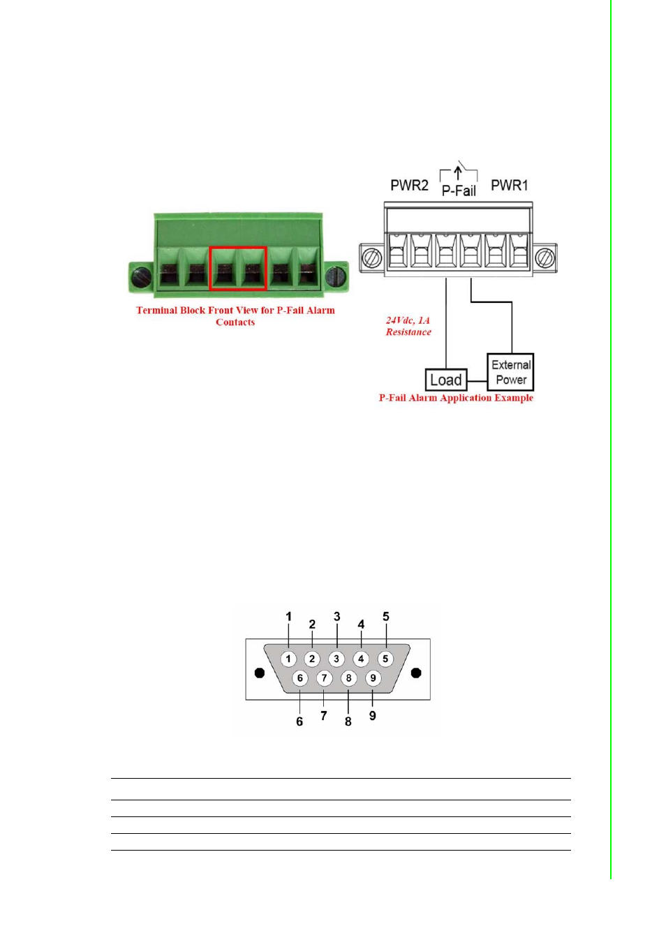
Connecting Power
The EKI-122X series supports dual +12 to 48 VDC power inputs and a power-fail
relay output. Following figure is the power terminal block pin assignments. Please
refer it to connect to the proper power requirements and polarity.
Figure 2.34 Power Connector
You can connect an alarm indicator, buzzer or other signaling equipment through the
power-fail relay output. The relay opens if power input V1 or V2 fails. (“Open” means
if you connect relay output with an LED, the light will be shut off)
2.4.3
Connecting Serial Devices
The EKI-122X series provides one, two or four standard serial ports DB9 (male)
connectors. RS-232/422/485 pin assignments are as below.
Figure 2.35 EKI-122X series Serial Port Pin Assignments
Pin
1
2
3
4
5
6
7
8
9
RS-232
DCD
RX
TX
DTR
GND
DSR
RTS
CTS
RI
RS-422
TX-
-
-
TX+
GND
-
RX+
-
RX-
RS-485
Data-
-
-
Data+
GND
-
-
-
-
- USOPTL4DR-LS - Datasheet (2 pages)
- ZXT9-IOA-KIT - Manual (75 pages)
- ADAM-6066 - Manual (272 pages)
- 855-11619--57 - Datasheet (2 pages)
- 851-10904 - Datasheet (2 pages)
- SS-BLT-100PR - Quick Start Guide (1 page)
- ISOCON-6 - Datasheet (2 pages)
- I-7060 - Manual (64 pages)
- AMU864 - Datasheet (2 pages)
- 714FX6-SC_ST - Manual (154 pages)
- 422LP25R - Datasheet (2 pages)
- ZP9D-115RM-LR - Manual (54 pages)
- EKI-6311GN-EU - Manual (56 pages)
- ZZ24D-NA(NB,NC,ND)-SR - Quick Start Guide (4 pages)
- ESCLP-100 - Manual (23 pages)
- 806-39753 - Datasheet (1 page)
- 485SD9RJ - Datasheet (1 page)
- 712FX4-SC_ST - Manual (154 pages)
- 850-18610 - Manual (18 pages)
- ESW208 Series - Datasheet (2 pages)
- VESR321_ML_SL - Quick Start Guide (3 pages)
- OP10 - Datasheet (1 page)
- RT3G-300_310_320_330_340-W - Configuration Manual (79 pages)
- EIRHP305-T - Datasheet (2 pages)
- EIRSP1 - Datasheet (1 page)
- 422TTL33 - Datasheet (2 pages)
- 485DRCI - Quick Start Guide (2 pages)
- I-7021_P - Datasheet (2 pages)
- NTSA-CAT5E - Datasheet (2 pages)
- 485COSR - Datasheet (2 pages)
- 855-10619--57 - Datasheet (2 pages)
- UH401SL_2KV - Datasheet (2 pages)
- 105FXE-SC(ST)-15-POE - Manual (19 pages)
- 102MC-FL_SC_ST - Manual (23 pages)
- CBL00302 - Datasheet (1 page)
- 850-18100--27 - Datasheet (2 pages)
- 850-10953-DC - Datasheet (2 pages)
- ESR904 - Datasheet (2 pages)
- 308TX-N - Datasheet (3 pages)
- 422LP25N - Datasheet (2 pages)
- 708FX2-SC_ST - Datasheet (3 pages)
- MESR321_SL_ML - Datasheet (2 pages)
- SL2736-698 - Quick Start Guide (8 pages)
- I-7188E Series - Datasheet (1 page)
- ANT-PAD58-19 - Datasheet (1 page)