B&B Electronics EIR508-T - Quick Start Guide User Manual
Quick start guide, Elinx managed ethernet switch eir508 series, Items included
EIR508 Series-1713qsg
1
2
3
4
5
o
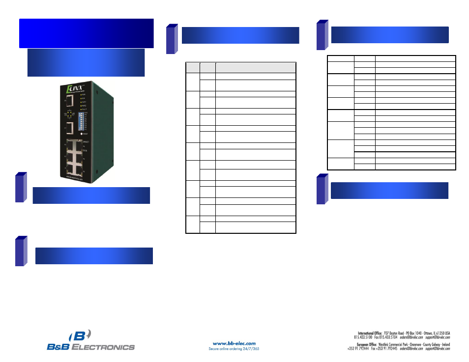
Ethernet Switch
o
CD with Support Manual
o
This Quick Start Guide
o
Panel Mount Bracket
o
IP Address: 192.168.16.1
o
Subnet Mask: 255.255.255.0
o
Gateway: 192.168.16.254
o
User Name: root, Password: root
o
Record the switch’s MAC Address in the space
provided. The MAC Address is printed on the product
label. Provide the MAC Address to your Network
Administrator. The Network Administrator should
provide an IP Address, Subnet Mask, and Gateway.
o
Select a mounting location and install with the attached
DIN rail clip or included panel mount kit.
o
Connect power to the switch
o
12 to 48 VDC
o
Redundant DC input is available with fault
contacts.
Pos
Status Description
1
OFF
Disable port 1 Alarm
ON
Enable port 1 Alarm
(If port 1 link fails, the fault LED will light)
2
OFF
Disable port 2 Alarm
ON
Enable port 2 Alarm
(If port 2 link fails, the fault LED will light)
3
OFF
Disable port 3 Alarm
ON
Enable port 3 Alarm
(If port 3 link fails, the fault LED will light)
4
OFF
Disable port 4 Alarm
ON
Enable port 4 Alarm
(If port 4 link fails, the fault LED will light)
5
OFF
Disable port 5 Alarm
ON
Enable port 5 Alarm
(If port 5 link fails, the fault LED will light)
6
OFF
Disable port 6 Alarm
ON
Enable port 6 Alarm
(If port 6 link fails, the fault LED will light)
7
OFF
Disable port 7 Alarm
ON
Enable port 7 Alarm.
(If port 7 link fails, the fault LED will light)
8
OFF
Disable port 8 Alarm
ON
Enable port 8 Alarm
(If port 8 link fails, the fault LED will light)
9
OFF
Disable the ring master function.
ON
Enable the switch as the ring master
in the redundant ring group.
LED
Status
Meaning
Power
Green
The Switch is powered on
Off
The Switch is powered off
Power 1
Green
Power Source 1 is available
Off
Power Source 1 is unavailable
Power 2
Green
Power Source 1 is available
Off
Power Source 2 is unavailable
Fault
Yellow
Power Source failure or Port Failure
Off
Normal Operation
R.M.
Green
Ring Master (Master of a redundant ring)
Off
The switch is not a Ring Master
LNK/ACT
Ports 7 & 8
Green
The port is linked
Blinking
The port is receiving or transmitting packets
Off
No device attached
FDX/COL
Ports 7 & 8
Yellow
Full Duplex Mode
Blinking
Data Collision
Off
Half Duplex Mode
10/100 Ports
Green
Yellow
Quick Start Guide
Elinx Managed Ethernet Switch
EIR508 Series
Items Included
Default Settings
DIP Switch Settings
LED Chart
Hardware Installation