Terminals electrical load, Power supplies, Ps5r standard series 116 – B&B Electronics PS5R Series - Datasheet User Manual
Page 4: Accessories, Overcurrent protection characteristics, Parallel operation, Installation instructions
PS5R Standard Series
116
www.idec.com
PLCs
Operator Interfaces
Automation Software
Power Supplies
Sensors
Communication & Networking
Power Supplies
Accessories
Part Numbers: PS5R Accessories
Appearance
Description
Part Number
DIN rail (1000mm)
BNDN1000
DIN rail end clip
BNL5
Overcurrent Protection Characteristics
PS5R-A/B
100
50
0
100105
Output V
oltage (%)
Output Current (%)
PS5R-C/D/E
100
50
0
100 105
Output V
oltage (%)
Output Current (%)
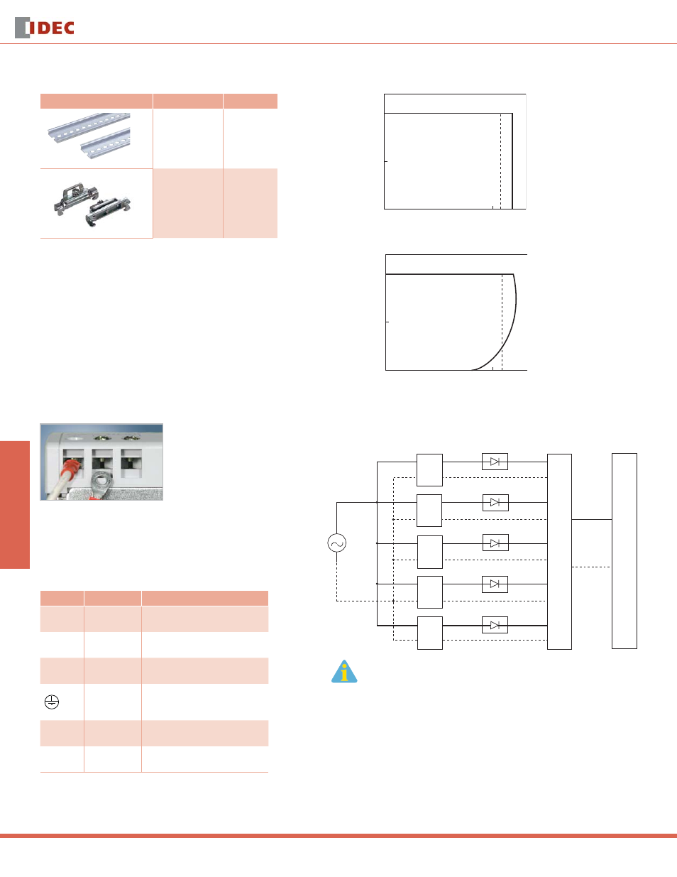
Parallel Operation
+
-
PS5R
PS5R
PS5R
PS5R
PS5R
TERMINALS
ELECTRICAL LOAD
1. Parallel operation only recommended for PS5R-Q24, PS5R-F24 and PS5R-G24.
2. Factory recommended diode ST Microelectronics BYV54V-50, BYV54V-100,
BYV54V-200, BYV541V-200 or with equivalent electrical specifi cations.
3. Using the voltage adjustment make sure out-voltage is the same for all power
supplies.
Installation Instructions
Time-Saving Spring-up Terminals
The innovative terminals on the PS5R series use a special,
spring-loaded screw. This makes installation as easy as pushing
down and turning with a screwdriver. Installation time is cut in
half since the screws do not need to be backed out to install
wiring. The screws are held captive once installed and are
100% fi nger-safe. Screw terminals accept bare wire or ring or
fork connectors.
1. Insert the wire connector into the slot on the side of the
power supply.
2. Using a fl at head or Phillips screwdriver, push down and turn
the screw.
The wire is now connected, and the screw terminal is fi nger-
safe!
Front Panel (terminals)
Markings
Name
Description
V. ADJ
Voltage
adjustment
Adjusts within ±10%; turn clockwise
to increase output voltage
DC ON
Operation
indicator
Green LED is lit when output voltage
is on
+V, –V
DC output
terminals
+V: Positive output Terminal
–V: Negative output terminal
Frame
ground
Ground this terminal to reduce
high-frequency currents caused by
switching
L, N
Input
terminals
Accept a wide range of voltages and
frequencies (no polarity at DC input)
NC
No connection
Do not insert wires here, as this may
damage the power supply