Communicating with the fieldbus gateway, Configuring a fieldbus gateway, Cables and drivers – B&B Electronics VFG3000 - Quick Start Guide User Manual
Page 6: Usb, data transfers from the compactflash card, Ethernet communications, Rs232 ports, Dh485 communications
6
CONFIGURING A FIELDBUS GATEWAY
The Fieldbus Gateway is configured using Fieldbus Gateway Manager.
Updates to the software for new features and drivers are posted on the website
as they become available. By configuring the Fieldbus Gateway using the latest
version of the software, you are assured that your unit has the most up to date
feature set. The software can configure the Fieldbus Gateway through the
RS232/PG port, USB/PG port, Ethernet, or CompactFlash. The USB/PG port is
connected using a standard USB cable with a Type B connector.
The driver needed to use the USB port will be installed with the software.
The RS232/PG port uses a programming cable made by B&B to connect to the
DB9 COM port of your computer. If making your own cable, refer to the
“Fieldbus Gateway Port Pin Outs” for wiring information.
The CompactFlash can be used to program a Fieldbus Gateway by placing a
configuration file and firmware on the CompactFlash card. The card is then
inserted into the target Fieldbus Gateway and powered.
CABLES AND DRIVERS
B&B has a wide range of cables and drivers for use with many different
communication types. A list of these drivers and cables along with pin outs is
available from B&B’s website. If making your own cable, refer to the “Fieldbus
Gateway Port Pin Outs” for wiring information.
USB, DATA TRANSFERS FROM THE
COMPACTFLASH CARD
In order to transfer data from the CompactFlash card via the USB port, a
driver must be installed on your computer. This driver is installed with the
software and is located in the folder C:\Program Files\B&B Electronics\Vlinx
Fieldbus Gateway Manager\Device after the software is installed. This may
have already been accomplished if your Fieldbus Gateway was configured
using the USB port.
Once the driver is installed, connect the Fieldbus Gateway to your PC with a
USB cable, and follow “Mounting the CompactFlash” instructions in the
Fieldbus Gateway Manager user manual.
Note that using the USB port for frequent data transfers is not recommended.
For frequent data transfers it is recommended that the Ethernet connection be
used. Through the Ethernet connection a web page can be set up to view logged
data. Refer to the Fieldbus Gateway Manager manual for details.
Note: The USB port is for system set-up and diagnostics and is not intended for
permanent connection.
ETHERNET COMMUNICATIONS
Ethernet communications can be established at either 10 BASE-T or 100
BASE-TX. The Fieldbus Gateway’s RJ45 jack is wired as a NIC (Network
Interface Card). For example, when wiring to a hub or switch use a straight-
through cable, but when connecting to another NIC use a crossover cable.
The Fieldbus Gateway Manager manual contains additional information on
Ethernet communications.
RS232 PORTS
The Fieldbus Gateway has two RS232 ports. There is the RS232/PG port and
the COMMS port. Although only one of these ports can be used for
programming, both ports can be used for communications with a PLC. The
RS232/PG port can be used for either master or slave protocols.
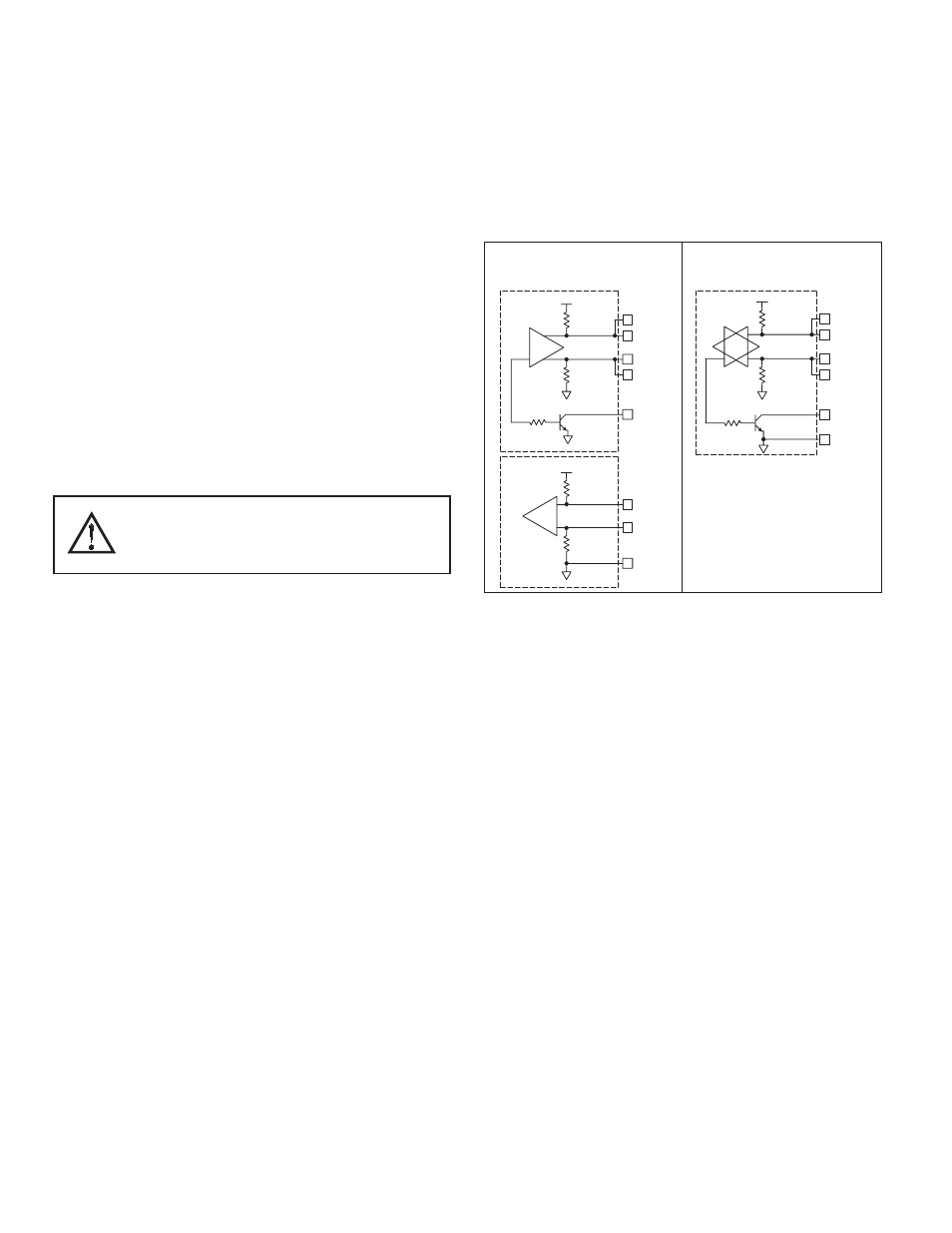
RS422/485 PORT
The Fieldbus Gateway has one RS422/485 port. This port can be configured
to act as either RS422 or RS485.
Note: All B&B devices connect A to A and B to B.
DH485 COMMUNICATIONS
The Fieldbus Gateway’s RS422/485 COMMS port can also be used for Allen
Bradley DH485 communications.
WARNING: DO NOT use a standard DH485 cable to connect this port to Allen
Bradley equipment. A cable and wiring diagram are available from B&B.
TX
5V
8
1
7
2
TxB
TxA
130K
130K
5
TxEN (OC)
RX
130K
5V
130K
RxB
4
RxA
3
GND
6
TxEN (OC)
TX/RX
130K
5
TxA
2
8
130K
5V
7
1
TxB
6
GND
RS422/485 4-WIRE
CONNECTIONS
RS485 2-WIRE
CONNECTIONS
COMMUNICATING WITH THE FIELDBUS GATEWAY
WARNING - DO NOT CONNECT OR DISCONNECT CABLES
WHILE POWER IS APPLIED UNLESS AREA IS KNOWN TO BE
NON-HAZARDOUS. USB PORT IS FOR SYSTEM SET-UP AND
DIAGNOSTICS AND IS NOT INTENDED FOR PERMANENT
CONNECTION.