Emc installation guidelines, Compactflash, Card – B&B Electronics VFG3000 - Quick Start Guide User Manual
Page 3: Power supply requirements
3
EMC INSTALLATION GUIDELINES
Although B&B Electronics Products are designed with a high degree of
immunity to Electromagnetic Interference (EMI), proper installation and wiring
methods must be followed to ensure compatibility in each application. The type
of the electrical noise, source or coupling method into a unit may be different
for various installations. Cable length, routing, and shield termination are very
important and can mean the difference between a successful or troublesome
installation. Listed are some EMI guidelines for a successful installation in an
industrial environment.
1. To reduce the chance of noise spikes entering the unit via the power lines,
connections should be made to a clean source. Connecting to circuits that also
power loads such as contactors, relays, motors, solenoids etc. should be avoided.
2. The unit should be mounted in a metal enclosure, which is properly connected
to protective earth.
3. Use shielded (screened) cables for all Signal and Control inputs. The shield
(screen) pigtail connection should be made as short as possible. The
connection point for the shield depends somewhat upon the application.
Listed below are the recommended methods of connecting the shield, in order
of their effectiveness.
a. Connect the shield to earth ground (protective earth) at one end where the
unit is mounted.
b. Connect the shield to earth ground at both ends of the cable, usually when
the noise source frequency is over 1 MHz.
c. Connect the shield to common of the Fieldbus Gateway and leave the other
end of the shield unconnected and insulated from earth ground.
4. Never run Signal or Control cables in the same conduit or raceway with AC
power lines, conductors feeding motors, solenoids, SCR controls, and
heaters, etc. The cables should be run through metal conduit that is properly
grounded. This is especially useful in applications where cable runs are long
and portable two-way radios are used in close proximity or if the installation
is near a commercial radio transmitter. Also, Signal or Control cables within
an enclosure should be routed as far away as possible from contactors, control
relays, transformers, and other noisy components.
5. Long cable runs are more susceptible to EMI pickup than short cable runs.
Therefore, keep cable runs as short as possible.
6. In extremely high EMI environments, the use of external EMI suppression
devices is effective. The following EMI suppression devices (or equivalent)
are recommended:
Ferrite Suppression Cores for signal and control cables:
Fair-Rite part number 0443167251
TDK part number ZCAT3035-1330A
Steward part number 28B2029-0A0
Line Filters for input power cables:
Schaffner part number FN610-1/07
Schaffner part number FN670-1.8/07
Corcom part number 1 VR3
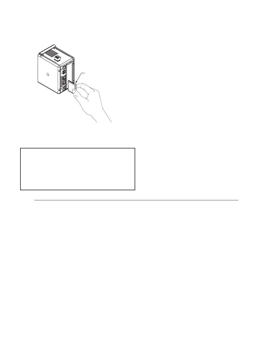
COMPACTFLASH
®
CARD
CompactFlash socket is a Type II socket that can accept either Type I or II
cards. Use cards with a minimum of 4 Mbytes and a maximum of 2 Gbytes with
the Fieldbus Gateway’s CompactFlash socket. Cards are available at most
computer and office supply retailers. CompactFlash can be used for configuration
transfers, data logging, and trending.
Information stored on a CompactFlash card can be read by a card reader
attached to a PC. This information is stored in IBM (Windows
®
) PC compatible
FAT16 file format.
CompactFlas
h
(Top Side)
CompactFlash-
Insert Top Side
Towards Left
Note: Do not remove or insert
the CompactFlash card while
power is applied.
POWER SUPPLY REQUIREMENTS
It is very important that the power supply is mounted correctly if the unit is
to operate reliably. Please take care to observe the following points:
– The power supply must be mounted close to the unit, with usually not more
than 6 feet (1.8 m) of cable between the supply and the Fieldbus Gateway.
Ideally, the shortest length possible should be used.
– The wire used to connect the Fieldbus Gateway’s power supply should be
at least 22-gage wire. If a longer cable run is used, a heavier gage wire
should be used. The routing of the cable should be kept away from large
contactors, inverters, and other devices which may generate significant
electrical noise.
– A power supply with an NEC Class 2 or Limited Power Source (LPS) and
SELV rating is to be used. This type of power supply provides isolation to
accessible circuits from hazardous voltage levels generated by a mains
power supply due to single faults. SELV is an acronym for “safety extra-
low voltage.” Safety extra-low voltage circuits shall exhibit voltages safe
to touch both under normal operating conditions and after a single fault,
such as a breakdown of a layer of basic insulation or after the failure of a
single component has occurred.
NOTE
For reliable operation of this and other B&B products, one of the
following brands of CompactFlash card must be used...
SimpleTech
SMART
®
Modular
SanDisk
®
Silicon Systems
Not all of the above manufacturers offer CompactFlash cards recognized
to UL standards, which may be required for your application.