B&B Electronics 232BRC - Datasheet User Manual
Page 2
232BRC-0812ds-2/2
© 2011 by B&B Electronics. All rights reserved.
www.bb-elec.com [email protected] [email protected]
International Office: 707 Dayton Road PO Box 1040 Ottawa, IL 61350 USA 815-433-5100 Fax 433-5104
European Office: Westlink Commercial Park Oranmore Co. Galway Ireland +353 91 792444 Fax +353 91 792445
PR
O
D
U
C
T
INF
ORM
A
TIO
N
B
&
B
ELE
C
T
R
ON
ICS
Operation
Refer to the Instruction Manual contained on the CD ROM.
The 232BRC has twoDB9 connectors. The female connector is configured as DCE for connecting
to PCs, terminals, and other DTE devices. The male connector is configured as DTE for connecting
to modems, and other DCE devices. Refer to Table One and Table Two for DB9 pin-outs.
Three LED’s indicate power and the presence of data in either port’s buffer.
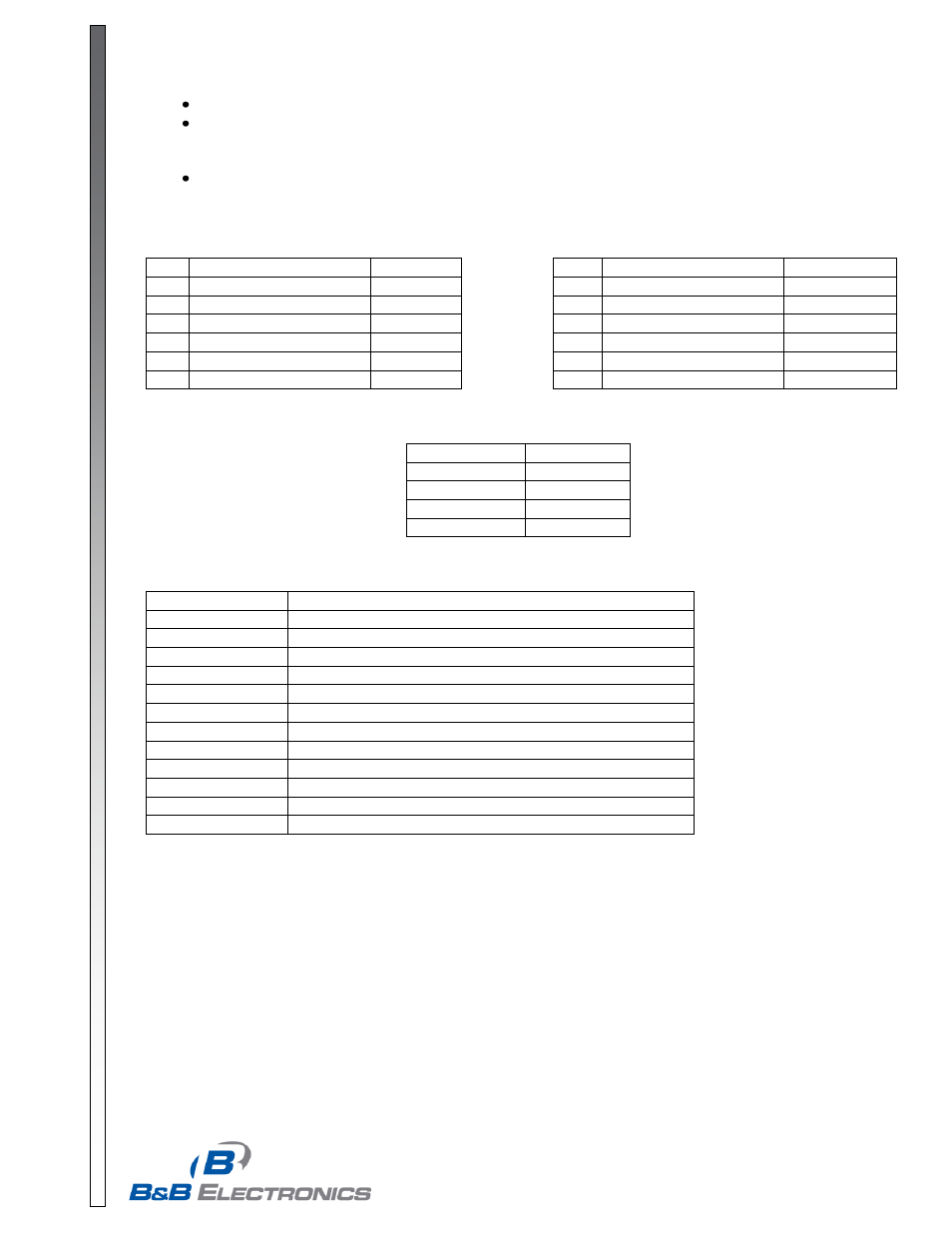
Table 1
Table 2
Port A DB9F (DCE)
Port B DB9M (DTE)
Pin
Signal
Direction
Pin
Signal
Direction
2
Receive Data (RD)
Output
2
Receive Data (RD)
Input
3
Transmit Data (TD)
Input
3
Transmit Data (TD)
Output
4
DTE Ready (DTR)
Input
4
DTE Ready (DTR)
Output
6
DCE Ready (DSR)
Output
6
DCE Ready (DSR)
Input
7
Request to Send (RTS)
Input
7
Request to Send (RTS)
Output
8
Clear to Send (CTS)
Output
8
Clear to Send (CTS)
Input
Table 3
Factory Default Parameters
Data Rate
9600 bps
Data Bits
8
Stop Bits
1
Parity
None
Handshaking
None
Specifications
Interface:
RS-232 Asynchronous
Data Bits:
5,6,7, or 8
Parity:
Even, Odd, or None
Data Rate:
300 to 115.2 kbps
Stop Bits:
1 or 2
Flow Control:
Hardware (RTS/CTS), Software (XON/XOFF), or None
Buffer Memory:
19 Kb SRAM
LEDs:
Buffer A, Buffer B, and Power
Input Voltage:
12 to 17 VDC @ 60mA max
Power Connector
2.5 mm jack (positive tip)
Data Connectors:
Port A DB9F (DCE), Port B DB9M (DTE)
Dimensions:
5.8 x 3.6 x 1.2 in (14.6 x 9.1 x 3.0 cm)
Software:
Windows 95, 98, NT, 2K, XP, Vista Compatible