B&B Electronics 9POP4 - Quick Start Guide User Manual
Quick start guide
Documentation Number –PN 9093R1 9POP4-0712qsg
©2010 B&B Electronics Manufacturing Company
C
C
e
e
r
r
t
t
i
i
f
f
i
i
c
c
a
a
t
t
i
i
o
o
n
n
s
s
FCC Class B
CE
o
EN 55022: 2006 + A1:2007 Class A Emissions
o
EN 61000-6-1: 2007 Generic Standards for
Residential, Commercial and Light-Industrial
Environments
o
EN 61000-4-2: 2008 Electro-Static Discharge
(ESD)
o
EN 61000-4-3: 2006 Radiated Field Immunity
(RFI)
o
EN 61000-4-4: 2004 Electrical Fast Transients-
Burst (EFT)
o
EN61000-4-5: Ed2, 2005 (Surge)
o
EN 61000-4-6: 2005 Conducted Immunity
C
C
h
h
e
e
c
c
k
k
f
f
o
o
r
r
A
A
l
l
l
l
R
R
e
e
q
q
u
u
i
i
r
r
e
e
d
d
H
H
a
a
r
r
d
d
w
w
a
a
r
r
e
e
9POP4 RS-232 Optical Isolator
This Quick Start Guide
12VDC Wall Power Supply (sold separately).
Recommended Power Supplies:
o
US – 232PS
o
UK – PS1UK-1000
o
EU – PS1EU-1000
I
I
n
n
f
f
o
o
r
r
m
m
a
a
t
t
i
i
o
o
n
n
–
–
C
C
o
o
n
n
n
n
e
e
c
c
t
t
o
o
r
r
s
s
Put
Quick Start Guide
9POP4
Optically Isolated RS-232
Repeater
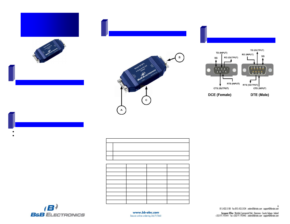
D
D
B
B
9
9
P
P
i
i
n
n
-
-
o
o
u
u
t
t
1. DTE stands for Data Terminal
Equipment: these include Computers,
PLC's, and most devices which are not
used to extend communications. Think
COMPUTER for DTE.
2. DCE stands for Data Communications
Equipment: these includes devices
intended to plug directly into a DTE
port, Modems and devices that extend
communications like a modem, such
as RS-422, RS-485, or Fiber Optic
converters or Radio Modems. Think
MODEM for DCE
.
3. On the DCE (female) side, Pins 1, 4,
and 6 are tied together internally.
4. On the DTE (Male) side, Pins 4 and 6
are tied together internally.
2
1
Connectors
A DB9 Female – Data Communications Equipment
(DCE)
A DB9 Male – Data Terminal Equipment (DTE)
C Power – 12 VDC Jack, 2.5 mm Center Positive
Pin
Signal
DCE
DTE
1
DCD
Output
Input
2
RD
Output
Input
3
TD
Input
Output
4
DTR
Input
Output
5
GND
---
---
6
DSR
Output
Input
7
RTS
Input
Output
8
CTS
Output
Input
9
RI
Output
Input
3
4