Front panel – B&B Electronics 100-POE-SPL-12 - Manual User Manual
Page 9
(Revised 8/5/2009)
9
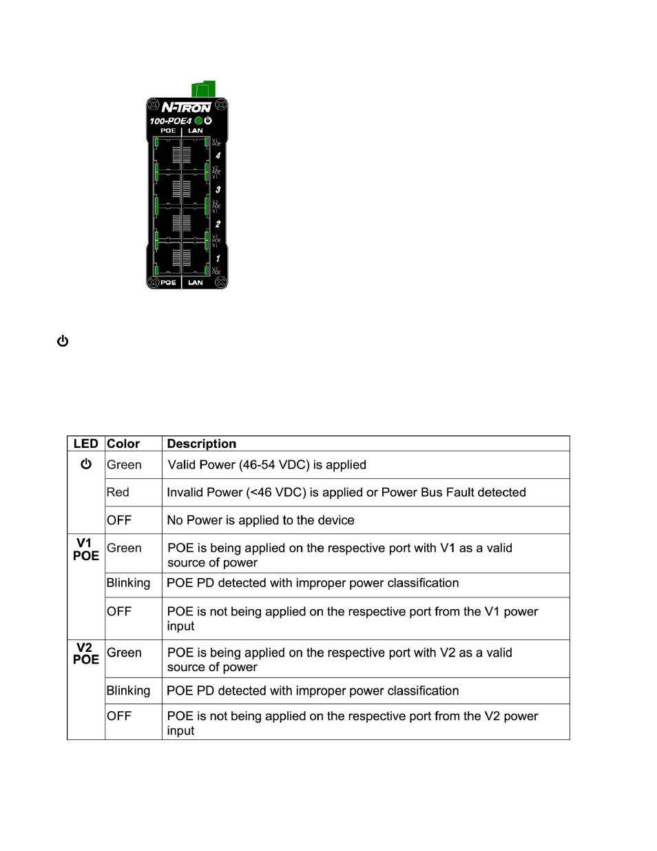
FRONT PANEL
From Top to Bottom:
Power LED
V1 POE
POE is being applied on the respective port with V1 as a valid source of power.
V2 POE
is being applied on the respective port with V2 as a valid source of power.
LEDs: The table below describes the operating modes (Port LEDs are for power supply status only and
do NOT indicate link or activity):
Note: Redundant power inputs will not balance the power load. Only load from one power supply is used
at a time.
See also other documents in the category B&B Electronics Accessories communication:
- USOPTL4DR-LS - Datasheet (2 pages)
- ZXT9-IOA-KIT - Manual (75 pages)
- ADAM-6066 - Manual (272 pages)
- 855-11619--57 - Datasheet (2 pages)
- 851-10904 - Datasheet (2 pages)
- SS-BLT-100PR - Quick Start Guide (1 page)
- ISOCON-6 - Datasheet (2 pages)
- I-7060 - Manual (64 pages)
- AMU864 - Datasheet (2 pages)
- 714FX6-SC_ST - Manual (154 pages)
- 422LP25R - Datasheet (2 pages)
- ZP9D-115RM-LR - Manual (54 pages)
- EKI-6311GN-EU - Manual (56 pages)
- ZZ24D-NA(NB,NC,ND)-SR - Quick Start Guide (4 pages)
- ESCLP-100 - Manual (23 pages)
- 806-39753 - Datasheet (1 page)
- 485SD9RJ - Datasheet (1 page)
- 712FX4-SC_ST - Manual (154 pages)
- 850-18610 - Manual (18 pages)
- ESW208 Series - Datasheet (2 pages)
- VESR321_ML_SL - Quick Start Guide (3 pages)
- OP10 - Datasheet (1 page)
- RT3G-300_310_320_330_340-W - Configuration Manual (79 pages)
- EIRHP305-T - Datasheet (2 pages)
- EIRSP1 - Datasheet (1 page)
- 422TTL33 - Datasheet (2 pages)
- 485DRCI - Quick Start Guide (2 pages)
- I-7021_P - Datasheet (2 pages)
- NTSA-CAT5E - Datasheet (2 pages)
- 485COSR - Datasheet (2 pages)
- 855-10619--57 - Datasheet (2 pages)
- UH401SL_2KV - Datasheet (2 pages)
- 105FXE-SC(ST)-15-POE - Manual (19 pages)
- 102MC-FL_SC_ST - Manual (23 pages)
- CBL00302 - Datasheet (1 page)
- 850-18100--27 - Datasheet (2 pages)
- 850-10953-DC - Datasheet (2 pages)
- ESR904 - Datasheet (2 pages)
- 308TX-N - Datasheet (3 pages)
- 422LP25N - Datasheet (2 pages)
- 708FX2-SC_ST - Datasheet (3 pages)
- MESR321_SL_ML - Datasheet (2 pages)
- SL2736-698 - Quick Start Guide (8 pages)
- I-7188E Series - Datasheet (1 page)
- ANT-PAD58-19 - Datasheet (1 page)