B&B Electronics MESP211D_T - Quick Start Guide User Manual
Product overview, Leds, Set up network
4
3
Set Up Network
1
Set Up Hardware
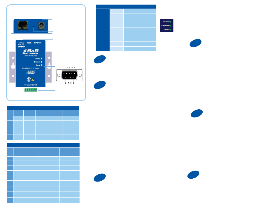
Product Overview
Power
10 - 30 VDC
If You Wish to Set Up TCP
2
Install/Setup
2. If a DHCP server is not available and the default address
does not work on your PC, change your PC network settings
to IP Address: 169.254.102.1, Subnet Mask: 255.255.0.0,
Default Gateway: 169.254.102.100.
If you are not able to use these settings in your installation,
refer to the User’s Manual for directions to change the
Gateway’s TCP/IP settings.
Note: The Vlinx Modbus Gateway Manager
software contains default parameter values that
are common to most Modbus networks.
1. TCP Settings:
“Connect to port” identifies TCP port used in TCP client
mode. Valid range is 1 to 65535. Default is 502. Response
timeout is the maximum response time.
Valid range is from 1 to 65535. Default is 100 ms.
2. TCP Server Settings:
“Listen on port” identifies TCP port in TCP server mode.
Valid range is from 1 to 65535. Default is 502. “Limit the
number of connections” controls the number of simultaneous
TCP clients that can be connected. Connection Filter Mode
options like “allow everyone,” “allow specific IP address”
and “allow a range of IP addresses” control which TCP
clients can connect.
LEDs
DB9M or
Terminal Block
Ethernet Port
Reset/Mode Switch
E D C B A
LEDs
Ready
OFF
Unit not Ready, or Unit is in
Console Mode
ON
During normal boot up
BLINK
Slow Blink - Normal Operation
Fast Blink - Device is Rebooting
Ethernet
OFF
No Network link
ON
Network link
BLINK
Network Activity
Serial
OFF
No Serial Port Activity
ON
Console Mode
BLINK
Data is being transmitted or
received
1. Connect RJ45 first. DHCP is enabled by default.
2. Power the device.
3. Connect the Serial Device.
1. Use included CD to install Vlinx Modbus Gateway
Manager. If Autorun does not start, go to “My
Computer” and select the CD drive.
-- To start the installation on a 32-bit version of Windows double-click
on: CDROM:\Windows\32-Bit\MESR32.exe.
-- To start the installation on a 64-bit version of Windows double-
click on: CDROM:\Windows\64-Bit\MESR64.exe.
2. To open Vlinx Modbus Gateway Manager: click Start/Programs/
B&B Electronics/Vlinx/Vlinx Modbus Gateway Manager/Modbus
Gateway Manager.
3. To configure via the network, select “Network”.
4. If you know the IP address, select “The device is
at this address,” and type in the IP address. If not,
select “I don’t know the IP address of the device.” Click
Connect. If the device does not connect, cycle (unplug-replug) the
power, then try again.
(Alternative Method: Open a web browser and type the IP address
of the Modbus Gateway in the Address Bar. When the Modbus
Gateway is found the Login window will appear.)
5. Click “Login”. Password is blank from factory.
No password is necessary.
Terminal Block Pinout
Pin RS-232
Direction
(RS-232) RS-422/RS-485 4W RS-485 2W
A
RTS
Output
TDA (-)
Data A (-)
B
TD
Output
TDB (+)
Data B (+)
C
CTS
Input
RDA (-)
****
D
RD
Input
RDB (+)
****
E
GND
****
GND
GND
DB9 Male Pinout
Pin
RS-232 Direction
(RS-232)
RS-422/485
4-Wire
RS-485
2-Wire
1
DCD
Input
RDA (-)
****
2
RXD
Input
RDB (+)
****
3
TXD
Output
TDB (+)
Data B (+)
4
DTR
Output
TDA (-)
Data A (-)
5
GND
****
GND
GND
6
DSR
Input
****
****
7
RTS
Output
****
****
8
CTS
Input
****
****
9
****
****
****
****
“I want DHCP” is preselected to set up the network using
dynamic IP addressing. The Gateway is set up at the factory to
receive an IP assignment from a DHCP Server.
1. If a DHCP Server is not available on your network, it will
default to 169.254.102.39.
5
Set Up Serial Port
Note: The Vlinx Modbus Gateway Manager
software contains default parameter values
that are common to most Modbus networks.
1. Change the Description of the serial port if
needed.
2. Set the Mode to RS-232, RS-422,
RS-485 (2 wire) or RS-485 (4 wire).
3. Set the Baud Rate to control the speed of the port. Valid
rates range between 75 and 230.4k bits per second.
4. Stop Bits controls the number of bits for end of
character.
5. Parity controls the error checking mode, with
options of No Parity, Odd, Even, Mark and Space.
6
Finish and Log Out
There are additional Modbus configuration pages that may
be accessed by selecting “Next” at the bottom of each
page, or by selecting the desired page from the
vertical list in the left-hand column.
Continued on the next page...