B&B Electronics 4WSD25OTB - Datasheet User Manual
Page 2
P#9150_4WSDxxOTB-0812ds - p2/4
www.bb-elec.com [email protected] [email protected]
International Office: 707 Dayton Road PO Box 1040 Ottawa, IL 61350 USA 815-433-5100 Fax 433-5104
European Office: Westlink Commercial Park Oranmore Co. Galway Ireland +353 91 792444 Fax +353 91 792445
PR
O
D
U
C
T
INF
ORM
A
TIO
N
B
&
B
ELE
C
T
R
ON
ICS
Operation
Configure operating mode using guidance in Table 1.
Common Applications are discussed in Figures 1 through 3.
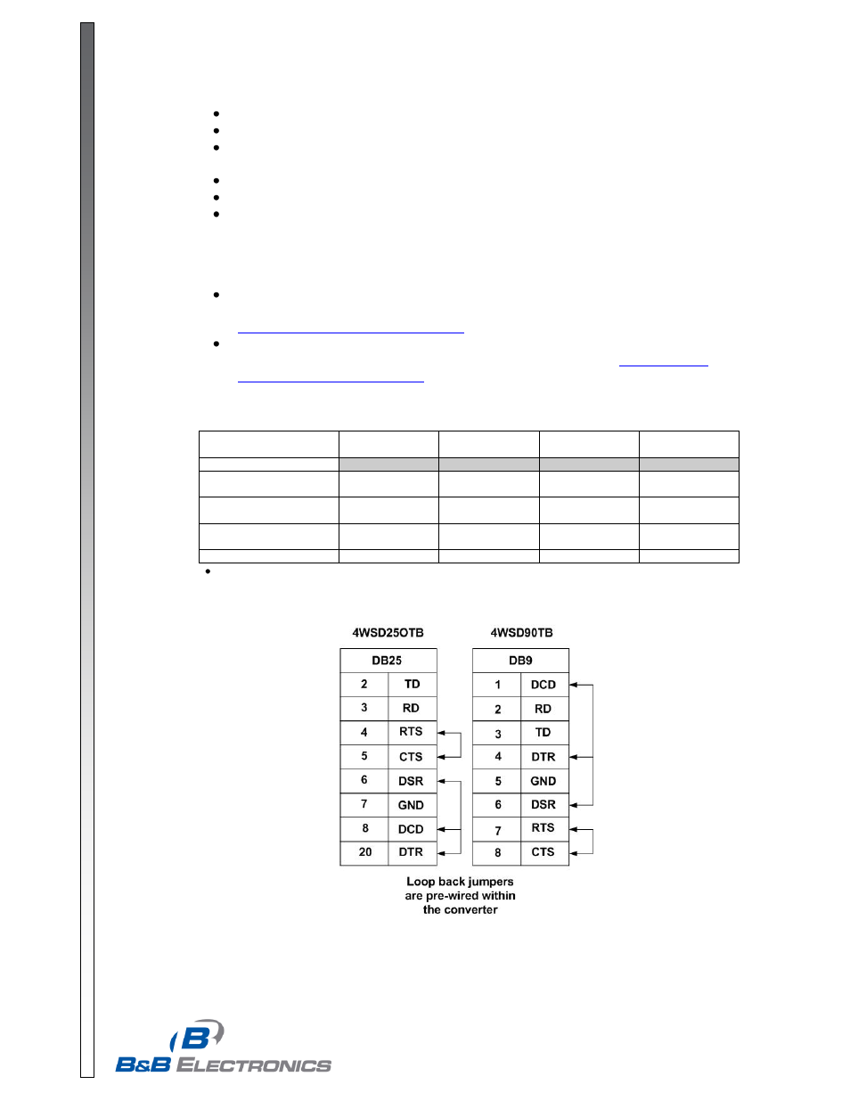
RS-232 connection requires RD, TD, and Signal Ground. The remaining signals are
looped back within the converter as shown in Table 2.
In half duplex operation, the receiver is enabled when not transmitting (Echo Off).
In RS-422 mode, the driver is always enabled.
In RS-485 mode, the RS-485 driver is automatically enabled during each space state by
the presence of an RS-232 signal. When the RS-232 data is in a mark or idle state, the RS-
485 driver is disabled and the RS-485 data lines are held in a mark state by the bias
provided by a 4.7K Ω resistor. The value of this resistor may need to be changed
depending on the termination used.
Refer to
B&B Electronics’ RS-422/RS-485 Application Note for detailed information
concerning RS-422 and RS-485 networks. This document is available for download at
The loopback test mode switch is used with hyper terminal to verify the operation of the
converter. Additional troubleshooting guidance is available a
Table 1
– Operating Mode Switch Settings
Switches
Switch 1 (Tx)
Switch 2 (Rx)
Switch 3
(bridge)
Switch 4
(bridge)
Operating Mode
RS-485 2-Wire Mode
(half duplex)
RS-485
Echo Off
2-Wire
2-Wire
RS-485 4-Wire Mode
(full duplex)
RS-485
Echo On
4-Wire
4-Wire
RS-422 4-Wire Mode
(full duplex)
RS-422
Echo On
4-Wire
4-Wire
Loopback Test Mode*
As Desired
Echo On
2-Wire
2-Wire
Used with HyperTerminal or another terminal program to confirm operation of data through converter.
Table 2
– RS-232 Pin-out