B&B Electronics 232MSS2 - Datasheet User Manual
B&B Electronics Accessories communication
232MSS2-0812ds -1/3
© 2003 by B&B Electronics. All rights reserved.
www.bb-elec.com [email protected] [email protected]
International Office: 707 Dayton Road PO Box 1040 Ottawa, IL 61350 USA 815-433-5100 Fax 433-5104
European Office: Westlink Commercial Park Oranmore Co. Galway Ireland +353 91 792444 Fax +353 91 792445
PR
O
D
U
C
T
INF
ORM
A
TIO
N
B
&
B
ELE
C
T
R
ON
ICS
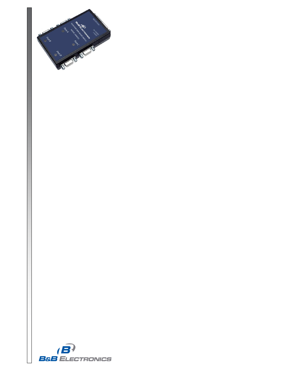
Model 232MSS2
RS-232 Four-Port Mini
Smart Switch/Port Combiner
Description
The RS-232 Four Port Mini Smart Switch/Port Combiner, Model 232MSS2, allows one RS-232 host device to connect
to as many as four RS-232 devices. The 232MSS2 can function as a software and/or hardware controlled switch. As a
software controlled switch, referred to as smart switch mode, the device connected to the master port of the 232MSS2
has control over which one of the four ports it is connected to. As a hardware controlled switch, referred to as port
combiner mode, the handshake lines of the devices connected to the four ports are used to gain access to the master
port. More details of smart switch and port combiner modes are covered later in this datasheet.
There are four LED's on the 232MSS2 to indicate which port is connected to the master port. The master port has a
DB-25S female connector and the slave ports have DB-9S female connectors. The master port can be configured as a
DTE or DCE port by an internal switch setting (See Table 1). If the master port is configured as a DTE port, the four
slave ports will become DCE ports. The 232MSS2 supports the following signals: TD, RD, RTS, and CTS. Handshake
lines DSR and DTR are connected together and are not passed through to the master port. There is no delay through
the device and data is not buffered. The 232MSS2 will work with baud rates from 1200 to 115,200 bps; 7 or 8 data bits;
even, odd or no parity; and 1 or 2 stop bits (7,N, 1 is not allowed). The communication format is set via dipswitch 1
(SW1 -- See Table 1).
NOTE: The data format and rates mentioned are used to switch the 232MSS2. Communication between the devices
can use any format or data rate.
Operation
Smart Switch Mode
The switch can be controlled in two different ways. The first way is referred to as smart switch mode. In this mode, the
switch is controlled by sending a programmable three-character preamble code to the "Master" port of the 232MSS2.
The first character of the preamble code must be the ASCI
I “Escape” character (decimal 27). The second character is
user programmable by setting Dipswitch 2 (SW2 -- See Table 2). The third character should be the ASCII upper case
letters A, B, C, or D to select the appropriate port. The third character can also
be the ASCII “EOT” (decimal 4)
character, which will turn off all the ports. Example: To select port “A”, send the ASCII “ESC” character, the
p
rogrammable character and the “A” character. When the 232MSS2 receives this code the master port will be
connecte
d directly to port “A”.
Port Combiner Mode
The other way to control the switch is referred to as port combiner mode. In port combiner mode, a slave port can gain
access to the master port by asserting a handshake line (CTS for DTE slave ports, RTS for DCE slave ports). If a slave
port asserts its handshake line and no other slave ports have their handshake line asserted, the master port will then be
connected directly to the slave port with the asserted handshake line. Once a slave port is connected to the master
port, the connection will remain until the slave disasserts its handshake line. If multiple slave ports have their
handshake lines asserted, access will be granted on a first come-first serve basis. If none of the slave ports have their
handshake line asserted, the switch can be controlled using the preamble codes.
Example: (Initial conditions--no slave ports with handshake lines asserted) In chronological order, Port C asserts its
handshake line, Port A asserts its handshake line, Port D asserts its handshake line and then Port C disasserts its
handshake line. When Port C asserts its handshake line, a connection will be made between the master port and Port
C. When Port C disasserts its handshake line, Port C will disconnected and Port A will be connected to the master port.
When Port A disasserts its handshake, Port A will be disconnected and Port D will be connected to the master port.