Calibrating the isocon – B&B Electronics ISOCON-3 - Manual User Manual
Page 13
ISOCON-3 USERS GUIDE
5. CALIBRATING THE ISOCON
When the unit is shipped the ISOCON will be calibrated for the input and output
types and ranges noted on the side label. If this label is blank then the unit will be
calibrated for 4-20mA input and 4-20mA source output.
If the unit is re-ranged by the user it is necessary to re-calibrate the unit to obtain
the maximum accuracy. The calibration is achieved by using both switches on the
front panel to select the zero or span input and then using the switches as
raise/lower buttons to adjust the output to the value required.
The mode the unit is in is indicated by the colour of the LED:
Green
-
Normal Operation
Red
- Span
Adjust
Yellow - Zero
Adjust
Setting of the zero and span points is non-interactive, so each point need only be
set once. A typical calibration sequence would be as follows:
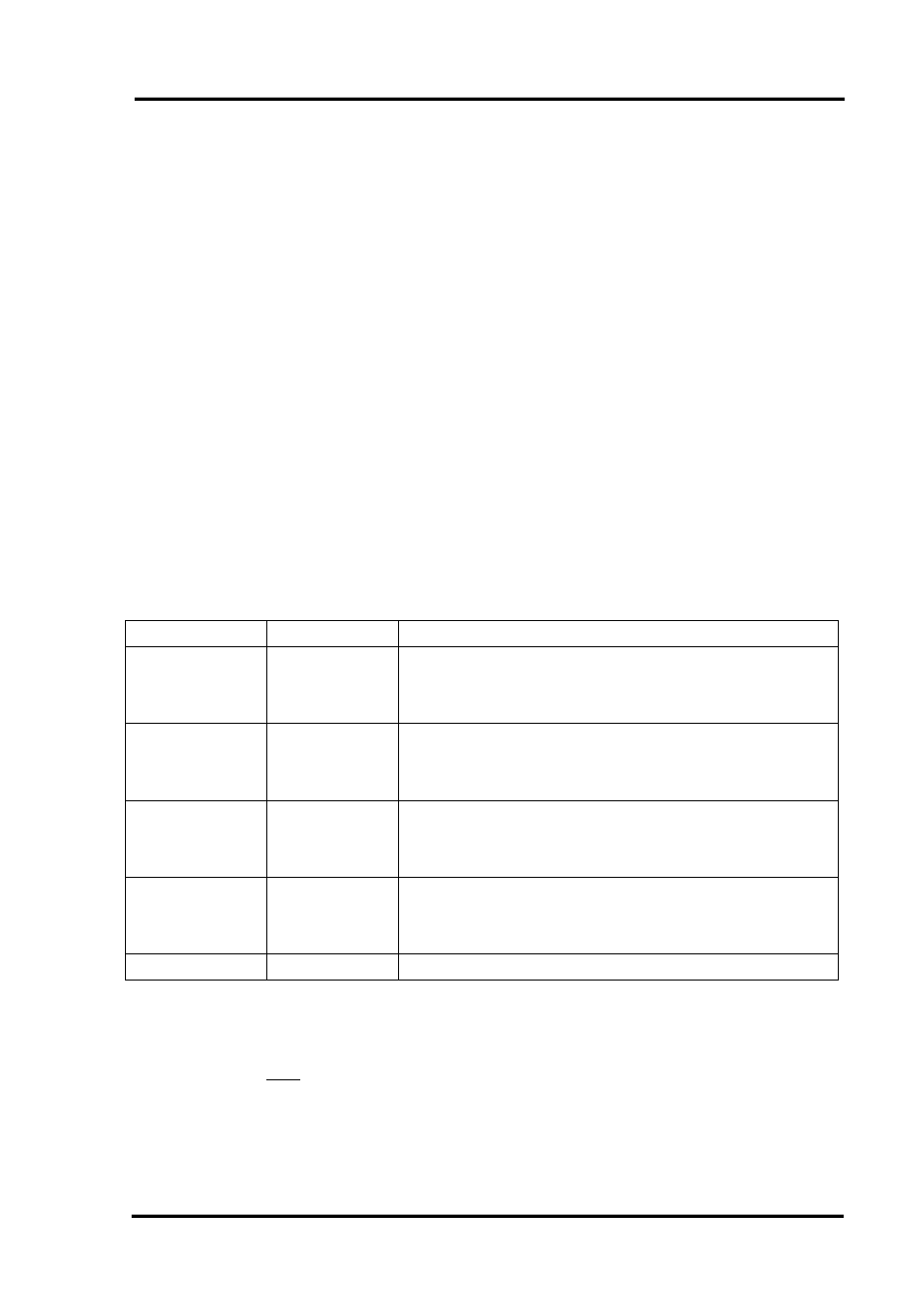
LED Colour Mode
Action
Green Normal
Apply full scale input.
Press and release both buttons together to enter
span mode
RED Span
Adjust
Press raise / lower buttons to adjust output value
Press and release both buttons together to return
to normal mode
Green Normal
Apply zero scale input
Press and release both buttons together to enter
zero mode
YELLOW Zero
Adjust
Press raise / lower buttons to adjust output value
Press and release both buttons together to return
to normal mode
Green Normal
Use
product
The unit is now calibrated and ready for use.
Note: The unit will retain the new settings on power down.
IIG060901 Page
13