Electrical characteristics (continued) – Rainbow Electronics MAX1541 User Manual
Page 6
MAX1540/MAX1541
Dual Step-Down Controllers with Saturation
Protection, Dynamic Output, and Linear Regulator
6
_______________________________________________________________________________________
Dual Mode is a trademark of Maxim Integrated Products, Inc.
PARAMETER
SYMBOL
CONDITIONS
MIN
TYP
MAX
UNITS
Valley Current-Limit Threshold
(Fixed)
V
LIM
_
(VAL)
V
CSP
_ - V
CSN
_, ILIM_ = V
CC
45
50
55
mV
V
ILIM
_ = 250mV
15
25
35
Valley Current-Limit Threshold
(Adjustable)
V
LIM
_
(VAL)
V
CSP
_ - V
CSN
_
V
ILIM
_ = 2.00V
170
200
230
mV
Current-Limit Threshold
(Negative)
V
NEG
V
CSP
_ - V
CSN
_, SKIP = ILIM_ = V
CC
,
T
A
= +25°C
-90
-65
-45
mV
Current-Limit Threshold
(Zero Crossing)
V
ZX
With respect to valley current-limit
threshold, V
CSP
_ - V
CSN
_, SKIP = GND,
ILIM_ = V
CC
2.5
mV
LSAT = V
CC
180
200
220
LSAT = open
157
175
193
Inductor-Saturation Current-Limit
Threshold
With respect to
valley current-
limit threshold,
ILIM_ = V
CC
LSAT = REF
135
150
165
%
ILIM_ Saturation Fault Sink
Current
I
ILIM
_
(LSAT)
V
CSP
- V
CSN
> inductor saturation current
limit, 0.25V < V
ILIM
_ < 2.0V
4
6
8
µA
ILIM_ Leakage Current
V
CSP
_ - V
CSN
_
< inductor saturation current
limit
0.1
µA
GATE DRIVERS
DH_ Gate-Driver On-Resistance
R
DH
BST_-LX_ forced to 5V
1.5
5
Ω
DL_, high state
1.5
5
DL_ Gate-Driver On-Resistance
R
DL
DL_, low state
0.6
3
Ω
DH_ Gate-Driver Source/Sink
Current
I
DH
DH_ forced to 2.5V, BST_-LX_ forced to 5V
1
A
DL_ Gate-Driver Source Current
I
DL
(SOURCE)
DL_ forced to 2.5V
1
A
DL_ Gate-Driver Sink Current
I
DL (SINK)
DL_ forced to 2.5V
3
A
DL_ rising
35
Dead Time
t
DEAD
DH_ rising
26
ns
INPUTS AND OUTPUTS
OD On-Resistance
R
OD
GATE = V
CC
10
25
Ω
OD Leakage Current
GATE = GND, OD forced to 5.5V
1
200
nA
Logic Input Threshold
ON1, ON2, SKIP, GATE rising edge,
hysteresis = 225mV
1.2
1.7
2.2
V
LDOON Input Trip Level
Rising edge, hysteresis = 250mV
1.20
1.25
1.30
V
Logic Input Current
ON1, ON2, LDOON, SKIP, GATE
-1
+1
µA
High
1.9
2.0
2.1
Dual Mode™ Threshold Voltage
FB1 (MAX1540),
FB2 (MAX1540/
MAX1541)
Low
0.05
0.1
0.15
V
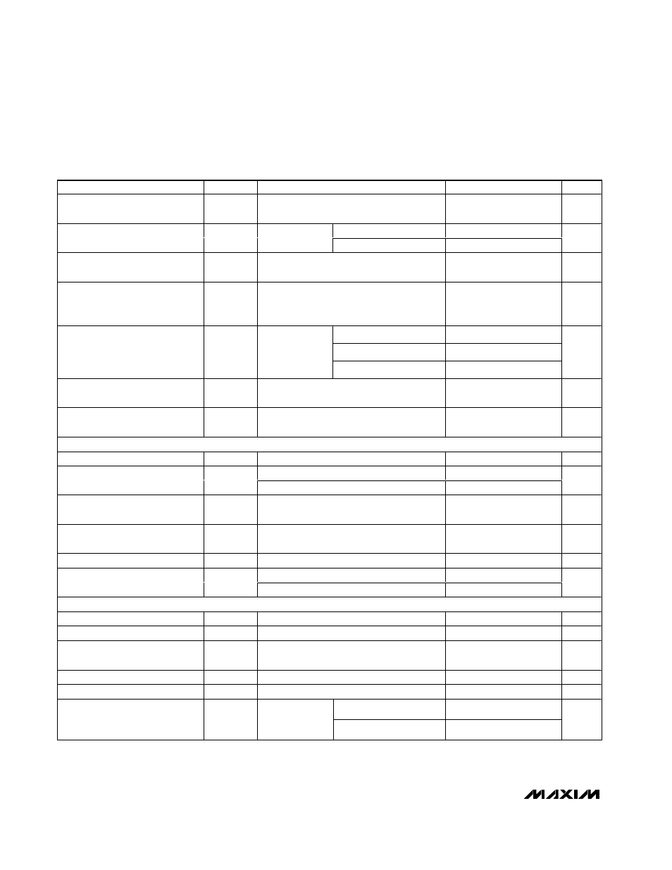
ELECTRICAL CHARACTERISTICS (continued)
(V+ = 15V, V
CC
= V
DD
= ON1 = ON2 = 5V, SKIP = GND, T
A
= 0°C to +85°C, unless otherwise noted. Typical values are at T
A
= +25
°C.)