Typical operating characteristics, Electrical characteristics (continued) – Rainbow Electronics MAX1541 User Manual
Page 10
MAX1540/MAX1541
Dual Step-Down Controllers with Saturation
Protection, Dynamic Output, and Linear Regulator
10
______________________________________________________________________________________
ELECTRICAL CHARACTERISTICS (continued)
(V+ = 15V, V
CC
= V
DD
= ON1 = ON2 = 5V, SKIP = GND, T
A
= -40°C to +85°C, unless otherwise noted.) (Note 4)
PARAMETER
SYMBOL
CONDITIONS
MIN
MAX
UNITS
High
V
CC
-
0.4V
Open
3.15
3.85
REF
1.65
2.35
Four-Level Input Logic Levels
TON, OVP/UVP, LSAT, SKIP,
FBLANK
Low
0.5
V
Note 1: For the MAX1540, the gate-driver input supply (V
DD
) is internally connected to the fixed 5V linear-regulator output (LDOOUT),
and the linear-regulator input supply (LDOIN) is internally connected to the battery voltage input (V+).
Note 2: When the inductor is in continuous conduction, the output voltage has a DC regulation level higher than the error-comparator
threshold by 50% of the ripple. In discontinuous conduction (SKIP = GND, light load), the output voltage has a DC regulation
level higher than the trip level by approximately 1.5% due to slope compensation.
Note 3: On-time and off-time specifications are measured from 50% point to 50% point at the DH_ pin with LX_ = GND, VBST_ = 5V,
and a 250pF capacitor connected from DH_ to LX_. Actual in-circuit times may differ due to MOSFET switching speeds.
Note 4: Specifications to -40°C are guaranteed by design, not production tested.
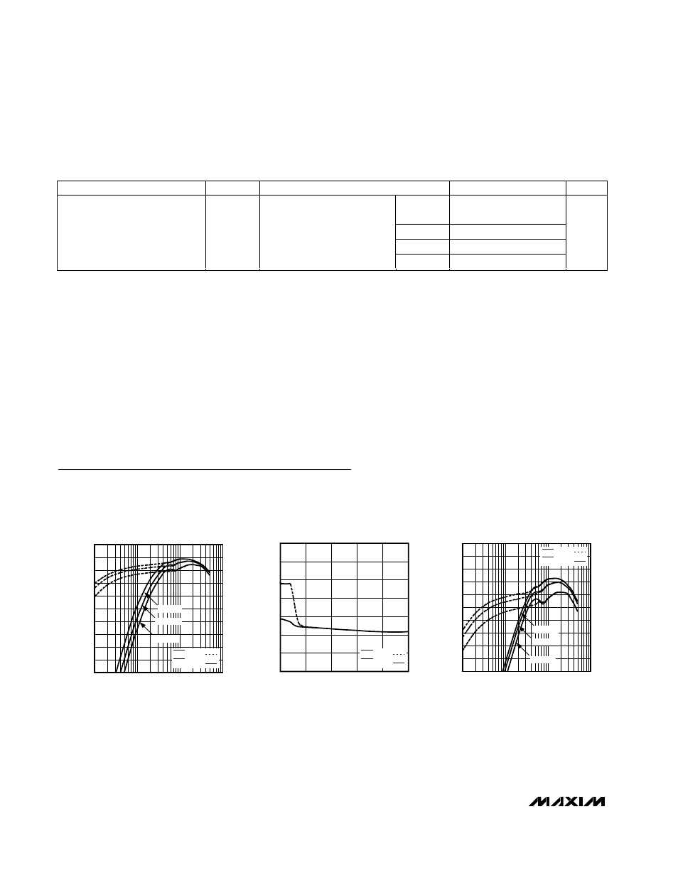
OUT2 EFFICIENCY vs. LOAD CURRENT
(V
OUT2
= 2.5V)
MAX1540 toc01
LOAD CURRENT (A)
EFFICIENCY (%)
1
0.1
55
60
65
70
75
80
85
90
95
100
50
0.01
10
SKIP = GND
SKIP = V
CC
V
IN
= 7V
V
IN
= 12V
V
IN
= 20V
2.5V OUTPUT VOLTAGE (OUT2)
vs. LOAD CURRENT
MAX1540 toc02
LOAD CURRENT (A)
OUTPUT VOLTAGE (V)
4
3
2
1
2.49
2.50
2.51
2.52
2.53
2.54
2.55
2.48
0
5
SKIP = GND
SKIP = V
CC
OUT1 EFFICIENCY vs. LOAD CURRENT
(V
OUT1
= 1.0V)
MAX1540 toc03
LOAD CURRENT (A)
EFFICIENCY (%)
1
0.1
55
60
65
70
75
80
85
90
95
100
50
0.01
10
SKIP = GND
SKIP = V
CC
V
IN
= 7V
V
IN
= 12V
V
IN
= 20V
Typical Operating Characteristics
(MAX1541 Circuit of Figure 12, V
IN
= 12V, V
DD
= V
CC
= 5V, SKIP = GND, TON = REF, T
A
= +25°C, unless otherwise noted.)